In manufacturing equipment and industrial equipment, couplings (shaft couplings) are used to accurately transmit power from a motor to a driven shaft. A coupling is a mechanical component that connects the drive shaft and the driven shaft, serving functions such as absorbing mounting misalignment and dampening vibrations.
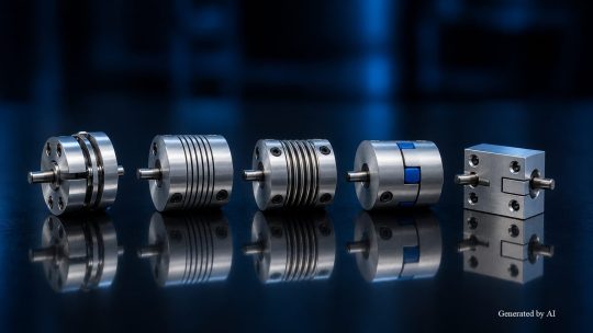
However, there are several types of couplings—including jaw-type, disc-type, and bellows-type—and selection must be based on the specific application and required characteristics.
This article provides a systematic explanation ranging from the basic functions of couplings to their main types and characteristics, as well as key points for selection. It also summarizes how to pair couplings with motors—essential knowledge for maximizing coupling performance during motor selection.
| Supervised by: C.I. TAKIRON Corporation Electronic Devices Sales Group This article has been supervised based on the advanced technical expertise and insights we have cultivated since our founding in 1919 as a leading company in plastic processing. Our department continuously analyzes market trends and the latest technologies in ultra-compact, high-precision micro motors, focusing on providing high-value-added information to designers and developers. As a team of experts with in-depth knowledge of product characteristics, we support our customers’ problem-solving and technological innovation by delivering accurate and practical content. |
目次:
Coupling Basics and Their Four Roles
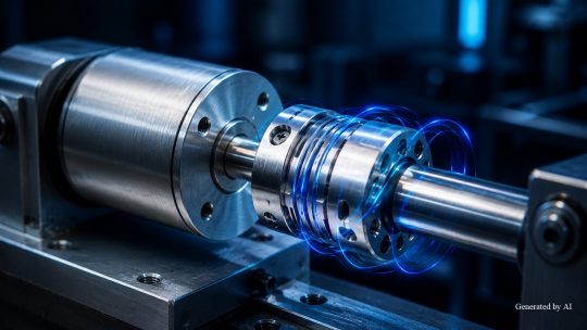
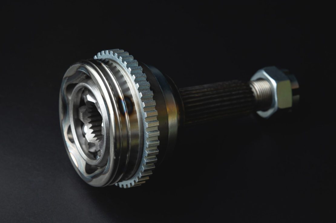
A coupling is a mechanical component that connects the drive shaft (the rotating side), such as a motor, to the driven shaft (the side being rotated), such as a pump or ball screw, to transmit power. Also known as a “shaft coupler” or “joint,” it is a component specifically designed for connecting machine shafts.
In addition to power transmission, couplings serve functions such as absorbing mounting misalignment, damping vibrations, and insulating against heat. Understanding each of these roles clarifies the selection criteria for equipment design.
Topics Covered in This Section
- Connecting the drive shaft and driven shaft to transmit power
- Absorbs three types of misalignment
- Dampening vibration and insulating against heat
A proper understanding of the roles of power transmission, misalignment compensation, vibration damping, and heat insulation clarifies the criteria for selecting couplings in equipment design.
Connecting the driving shaft and driven shaft to transmit power
Connecting the drive shaft and driven shaft to transmit power is the most fundamental role of a coupling. It connects the motor’s output shaft to the driven shaft—such as a ball screw or pump—and accurately transmits rotational power.
If a machine were manufactured with a structure in which the shafts are integrated, it would not only pose challenges in terms of machining precision and cost, but would also require additional labor for transportation and assembly. Furthermore, if either the drive side or the driven side were to fail, the entire unit would have to be replaced, increasing the maintenance burden.
By connecting the shafts via a coupling, power can be transmitted even between shafts of different diameters. In the event of damage, only the affected part needs to be replaced, allowing for a design that takes shaft connection and maintenance into account.
Compensating for Three Types of Misalignment
Another key role of a coupling is its ability to accommodate three types of misalignment. Misalignment refers to the deviation between the centerlines of the drive shaft and the driven shaft. The main types are as follows:
| Type | Description |
| Eccentricity (Parallel Misalignment) | A state in which the axes of the two shafts are offset in parallel |
| Angular Misalignment (Angular Shift) | A condition in which the axes of two shafts are tilted at an angle to each other |
| End Play (Axial Misalignment) | A condition in which two shafts move apart or come closer together in the axial direction |
If misalignment is left unaddressed, it can lead to equipment problems such as vibration, noise, and uneven bearing wear.
Since there are individual variations in machining accuracy among parts, it is practically difficult to assemble all shafts so that they are perfectly aligned. Couplings utilize the deformation of elastic materials or metal springs to absorb these three types of misalignment within acceptable limits, thereby reducing the load on surrounding components
Vibration Damping and Heat Isolation
Vibration damping and thermal isolation are also important functions of couplings. If vibrations generated during motor rotation are transmitted to driven-side equipment, such as ball screws, this can lead to a decrease in positioning accuracy and a deterioration in mechanical performance. Couplings function as shock absorbers that absorb vibrations from the drive side and maintain the accuracy of the driven side.
In addition, attention must be paid to the heat generated during motor operation. If heat is transmitted directly to the driven side, components such as ball screws may undergo thermal expansion, which could affect dimensional accuracy. The coupling suppresses heat transfer between the drive side and the driven side, preventing component deformation and misalignment.
Both vibration damping and thermal isolation are critical to maintaining the overall precision of the equipment and managing the load on surrounding components, thereby contributing to an extended lifespan.
Main Types and Characteristics of Couplings
Couplings are classified into several types based on their structural differences. Since torsional rigidity, vibration absorption, and the amount of misalignment they can accommodate vary by type, it is necessary to understand the characteristics of each type before making a selection.
Topics Covered in This Section
- Differences Between Rigid and Flexible Couplings
- Characteristics of Disc, Slit, and Bellows Types
- Characteristics of Jaw-Type and Rubber-Type Couplings
By understanding the structure and optimal applications of each type, you can efficiently narrow down your selection to find a coupling that meets your equipment’s requirements.
Differences Between Rigid and Flexible Couplings
Understanding the difference between rigid and flexible couplings is the starting point for coupling selection. The table below compares the main characteristics of the two types.
| Item | Rigid Couplings | Flexible Coupling |
| Structure | Two shafts are firmly integrated | Connected via an elastic element or metal spring |
| Misalignment Compensation | Not supported | Compatible with eccentricity, angular misalignment, and end play |
| Torsional rigidity | Torsional rigidity | Varies by typ |
| Cost | Relatively inexpensive | Varies depending on the structure |
| Suitable Environment | Conditions where there is virtually no axial misalignment | Conditions where installation errors or thermal expansion are present |
Since rigid couplings lack flexibility, they cannot accommodate installation errors and are used under conditions where shaft misalignment is minimal. Rigid couplings are the choice when a simple structure and high torsional rigidity are prioritized.
Flexible couplings transmit power while absorbing misalignment by utilizing the deflection of elastic elements or metal springs. Selecting the appropriate type based on design conditions is critical to equipment performance.
Features of Disc, Slit, and Bellows Types
Disc, slit, and bellows-type couplings are metal spring-based couplings that utilize the elastic deformation of metal to absorb misalignment. The structure and characteristics of each type are as follows.
| Type | Structural Features | Structural Features |
| Disc | Absorbs axial misalignment through the deflection of thin metal sheets | High torsional rigidity and low rotational transmission error |
| Slit | Integral structure formed by machining spiral slits into a cylindrical material | Compact, low-inertia, and simple design |
| Bellows | Compensates for displacement in three directions through the expansion and contraction of a metal bellows | Excellent rotational uniformity, ideal for connection with encoders |
Disc-type, metal-slit-type, and bellows-type models are available in backlash-free versions and are selected for applications such as servo motors, stepper motors, and encoder connections depending on the specific use. Some disc-type and metal-slit-type models are certified as oil-resistant.
Features of Jaw-Type and Rubber-Type Couplings
Jaw-type and rubber-type couplings are elastic couplings that incorporate elastic materials such as rubber or urethane as intermediate components. The jaw-type features a structure in which an elastomer is sandwiched between two metal hubs, providing excellent shock and vibration absorption. Easy installation is one of the key features of the jaw-type.
[Main Applications of Flexible Couplings]
- Power transmission for pumps, conveyors, and other equipment
- Vibration reduction in equipment subject to impact loads
- Suppression of hunting in servo motors
Some couplings that use high-damping rubber suppress hunting in servo motors, enabling higher gain settings. While couplings using high-damping rubber offer excellent vibration absorption characteristics, their torsional stiffness and allowable misalignment vary by product.
For equipment subject to vibration and shock, elastic couplings are a strong choice.
Basic Coupling Selection Procedure and Relationship to the Motor
The coupling selection process begins with selecting the appropriate type based on the motor and application, then proceeds step-by-step to size selection, confirmation of specifications such as allowable torque and allowable misalignment, and confirmation of the shaft connection method. Additionally, the type and characteristics of the motor to be paired with the coupling are factors that influence the selection results.
Here, we explain the practical motor selection procedure and its relationship to the motor.
Contents Covered in This Section
- How to Narrow Down the Type Based on the Application
- How to Verify Allowable Torque and Misalignment Tolerances
- How Motor Characteristics Affect Coupling Selection
By keeping in mind the key points to check at each stage of the selection process, you can more easily select a coupling that suits your application and operating conditions.
How to Narrow Down Options Based on Application
Narrowing down the options based on the application is the first step in selecting a coupling. The type of coupling is selected according to the type of motor and the intended application.
| Application Categories | Application Categories | Examples of Suitable Types |
| Motion Control (Positioning Control) | Zero Backlash High torsional rigidity | Disc/Slit |
| Power Transmission | High Torque Transmission Shock Absorption Allowable misalignment | Joe Oldham |
For motion control applications, rotational play compromises positioning accuracy, so it is necessary to select a zero-backlash type. On the other hand, for applications where power transmission is a priority, it is important to select a coupling that meets the required torque and verifies the allowable torque.
After narrowing down the types, proceed to selecting a size where the corrected torque is within the allowable torque range, verifying the shaft bore diameter, selecting the fastening method, and performing a final dimensional check. By checking these items in order, it becomes easier to narrow down the candidates.
How to Verify Allowable Torque and Misalignment Tolerance
Verifying the allowable torque and misalignment tolerance is a step undertaken during the coupling sizing process.
[Size Selection Verification Procedure]
- Calculate the corrected torque by multiplying the motor’s maximum torque by the correction factor
- Selecting a coupling size such that the corrected torque is equal to or less than the coupling’s allowable torque
- Verify that the misalignment values for eccentricity, angular misalignment, and end play are within the allowable limits
If misalignment exceeds the allowable limits, it may cause vibration or rapidly reduce the coupling’s lifespan.
A point requiring particular attention is that when two or more types of misalignment—such as eccentricity and angular misalignment—occur simultaneously, the allowable values for each are generally limited to half of their individual values. Since complex misalignments often occur in actual installation environments, a design that keeps the total misalignment within one-third of the allowable value is recommended.
Please determine the appropriate size for your equipment while also confirming the available space, shaft bore diameter, and fastening method.
The Impact of Motor Characteristics on Coupling Selection
The impact of motor characteristics on coupling selection is a critical factor that determines the overall performance of the system and must not be overlooked. When combining a coupling with a control motor (such as a servo motor), using a coupling with low torsional rigidity can cause a misalignment in the rotational angles between the motor side and the load side, which may compromise positioning accuracy. On the other hand, for applications where vibration suppression is required, a coupling with excellent vibration-damping properties and low susceptibility to resonance is the appropriate choice.
The appropriate coupling characteristics vary depending on the type of motor.For applications requiring high-speed, high-precision positioning control, high-rigidity disc-type or slit-type couplings with zero backlash are the leading choices. In applications where vibration absorption is a priority, adopting a rubber-type coupling with high damping capacity allows you to maximize motor performance while preventing system resonance. For general-purpose motors, where continuous rotation in one direction is the primary requirement, Oldham-type or jaw-type couplings—which offer a high tolerance for misalignment—are the main options.
In addition, the vibration characteristics and rotational accuracy of the motor itself directly affect the load on the coupling. For example, using a motor with minimal cogging (rotational irregularities) reduces the irregular forces acting on the coupling and improves the stability of the entire system. When selecting a coupling, it is essential to consider not only the allowable torque and misalignment tolerance listed in the catalog but also the quality of the motor serving as the drive source.
Summary
A coupling is a mechanical component that connects a driving shaft to a driven shaft to transmit power. In addition to power transmission, it serves to compensate for mounting errors (misalignment), absorb vibrations and shocks, and minimize the transfer of heat from the motor to the driven side.
Couplings come in various types, including disc, jaw, Oldham, bellows, and rigid types. When selecting a coupling, narrow down the options based on the application and motor type, and ensure that the correction torque does not exceed the allowable torque while verifying the allowable values for eccentricity, angular misalignment, and end play.
Additionally, when selecting a coupling, it is necessary to verify the type of motor to be paired with it and the operating conditions. When considering a motor-coupling combination, select the coupling type based on the required positioning accuracy and vibration damping performance. If you are looking for compact, high-precision motors, please visit the C.I. Takiron Corporation product website.
Product Information & Inquiries
For more details on C.I. Takiron’s micro motor products, please visit the website below.
- Product Site: https://cik-ele.com/en/
- Coreless Motors: https://cik-ele.com/en/products/list/coreless_motor/
- Brushless Motors: https://cik-ele.com/en/products/list/brushless_motor/
- Geared Motors: https://cik-ele.com/en/products/list/gearhead/
- Encoders: https://cik-ele.com/en/products/list/encoder/
If you are having trouble selecting a small motor for your product development, please feel free to contact us via the inquiry form. Our technical staff will discuss your application and requirements with you and propose the optimal solution.
- Inquiries: https://cik-ele.com/en/contact/