Brushed motors are widely adopted across diverse fields such as industrial equipment, medical equipment, and security equipment. Their simple structure and ease of control make them a preferred choice for many product development engineers.
However, many engineers also have specific needs: "I want to accurately understand the operating principle of a brushed motor," "I want to perform motor selection for my company's products," or "I want to clearly grasp the differences between brushed motors and Brushless motors."
This article comprehensively explains Brushed motors from an engineer's perspective, covering everything from their basic structure and rotation principle to their power generation principle and practical characteristics. We also introduce selection points useful for product development, suitable for everyone from new engineers to seasoned technicians, so please read to the end.
目次:
BASIC STRUCTURE AND OPERATING PRINCIPLE OF BRUSHED MOTORS
Brushed motors are simple-structured motors that can be driven by a DC power supply.
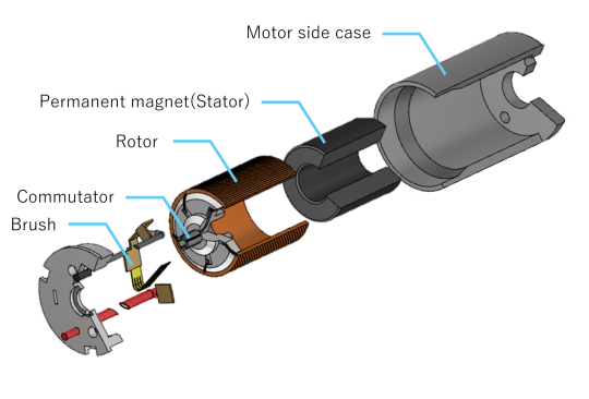
Brushed motors consist of four main components: the rotor, stator, brushes, and commutator. The mechanism works as follows: electric current supplied from the DC power supply passes through the brushes to the commutator, flows into the rotor winding, and generates rotational force based on Fleming’s left-hand rule.
The mechanical contact between the brushes and commutator enables the commutation action, where the current direction mechanically switches in response to rotor rotation, achieving continuous rotation. This mechanism is the motor's key feature, allowing it to be driven simply by connecting directly to a DC power supply without requiring an external control circuit.
Topics covered in this section
- The Role of the rotor and winding
- Rectification action via brushes and commutator
- Fleming’s left-hand rule and the principle of rotation
Let's start by understanding the basic structure and principles.
| THE ROLE OF THE ROTOR AND WINDING |
In some Brushed motors, the rotor consists of a winding fixed to the rotor shaft and an iron core. When electric current flows, a magnetic field is generated. The interaction between this generated magnetic field and the permanent magnet (or electromagnets) on the stator produces rotational torque, converting it into continuous rotational motion. The rotor's iron core typically has a laminated structure using electrical steel sheets, designed to enhance magnetic efficiency while minimizing eddy current losses.
The torque characteristics and rotational speed are determined by the winding design and number of poles, necessitating optimization for the specific application. For example, using thicker wire reduces resistance, allowing higher electric current flow and facilitating high torque. However, within the same space, this reduces the number of turns, increasing the speed constant (Kv) and resulting in characteristics favoring high-speed rotation.
Conversely, using a finer wire to achieve a higher number of turns increases resistance, reducing the electric current flow. However, the increased number of turns results in a larger torque coefficient (Kt), yielding characteristics that deliver strong torque at low speeds.
Thus, the combination of winding diameter and number of turns allows for adjusting the balance between torque performance and rotational speed.
Medical and optical equipment demand high-precision rotational control, making winding design a critical factor in product performance. Industrial tools prioritize high torque, while security equipment emphasizes power efficiency; thus, the optimal winding design varies by application.
| RECTIFICATION BY BRUSHES AND COMMUTATOR |
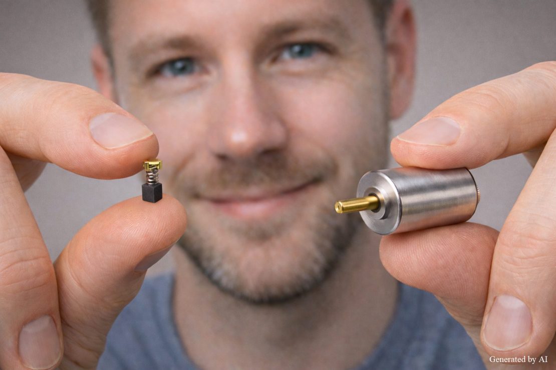
The brush is a stationary conductive component that supplies electric current while making contact with the rotating commutator. Brush materials, such as carbon or precious metal alloys, are selected with a balance between conductivity and wear resistance being crucial. The commutator is a cylindrical component divided into multiple segments. As the rotor rotates, the contact points with the brush switch, mechanically reversing the direction of electric current flowing through the winding.
A higher number of segments enables smoother commutation and reduces torque ripple (rotational irregularity). As the rotor turns, the brush sequentially switches segments, changing the electric current at precise moments to consistently generate rotational force in the same direction. This mechanical commutation allows stable, continuous rotation without external control.
The contact between the commutator and brushes ensures reliable operation despite the simple structure, underpinning the reliability of brushed motors. Their long-standing adoption across diverse fields, including industrial equipment and security equipment, attests to the robustness of this commutation mechanism.
| FLEMING’S LEFT-HAND RULE AND ROTATION PRINCIPLE |
The rotational principle of brushed motors is based on Fleming’s left-hand rule. According to this rule, when the thumb, index finger, and middle finger of the left hand are spread at right angles, aligning the middle finger with the direction of the electric current and the index finger with the direction of the magnetic field, the thumb indicates the direction of the force.
When electric current flows through a conductor (winding) placed in a magnetic field, a force is generated perpendicular to both the current direction and the magnetic field direction. This force generates rotational torque on the rotor. Through the commutation of current direction by the commutator and brushes, the rotor rotates continuously in the same direction.
Although design specifics vary, the commutator segments switch at regular rotor angles, reversing the electric current direction in the windings. This ensures the rotational force direction remains constant. This continuous commutation action maintains smooth rotational motion.
This simple and clear physical principle underpins the high reliability and controllability of brushed motors. Their long-standing adoption across diverse fields, such as industrial equipment and security equipment, attests to the robustness of this fundamental principle.
GENERATION PRINCIPLE AND CHARACTERISTICS OF BRUSHED MOTORS
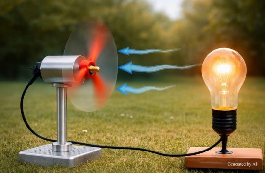
Brushed motors possess reversibility, functioning not only as motors but also as generators (dynamos). A generator (dynamo) is a device that converts rotational motion into electrical energy, and brushed motors possess this bidirectional conversion capability.
When mechanically rotated from an external source, an electromotive force is generated in the winding, enabling direct current power to be extracted via the brushes and commutator. This power generation principle also plays a crucial role during motor operation as back electromotive force (Back EMF).
When the motor rotates, back EMF is generated, limiting the supply electric current and enabling self-regulation proportional to rotational speed. Furthermore, during sudden stops, the increased back EMF allows for adjustment of braking force via short-circuit braking.
Topics covered in this section
- back electromotive force (Back EMF) and torque characteristics
- Short-Circuit Braking (short-circuit braking) Mechanism
- Relationship between Voltage, electric current, and Speed
Understanding the generation principle and characteristics enables optimal design for speed control and braking systems.
| BACK ELECTROMOTIVE FORCE (BACK EMF) AND TORQUE CHARACTERISTICS |
During motor rotation, back EMF generated when the windings cross the magnetic field acts in the opposite direction to the applied voltage, reducing the actual electric current. The magnitude of the back EMF is precisely proportional to the rotational speed. Therefore, higher rotational speeds generate greater back EMF, resulting in current limitation.
Consequently, the motor exhibits self-regulating characteristics: it rotates at high speed under no load, and as load increases, rotational speed decreases while torque increases.
Specifically, the voltage difference between the applied voltage and the counter-EMF is the effective voltage that actually drives the motor. As load torque increases, rotational speed decreases, reducing the counter-EMF. This allows more electric current to flow, generating the required torque. Since the magnitude of the counter-EMF is proportional to rotational speed, this principle is also applied in sensorless speed control.
This characteristic allows the motor's operating state to be determined without external sensors, contributing to simplified control systems and cost reduction. In medical equipment and industrial tools, this self-regulating characteristic is highly valued for its ability to handle load variations.
| HOW SHORT-CIRCUIT BRAKING WORKS |
When the motor terminals are short-circuited, the rotor, rotating due to inertia, acts as a generator (dynamo), causing electric current to flow through the short-circuit path. This electric current interacts with the magnetic field, generating a braking torque that resists rotation. The magnitude of this braking torque is proportional to the rotational speed. Consequently, stronger braking force is achieved at higher rotational speeds, and the braking force gradually weakens as the motor approaches a stop.
| Item | Characteristics |
| Braking Method | Electrical Braking (No Mechanical Friction) |
| Response | Rapid and stable stopping |
| Primary Applications | Precision positioning, emergency stop systems |
| Durability | Fewer direct wear parts for long service life |
Unlike mechanical brakes, it does not experience component wear or heat generation due to friction, making it resistant to performance degradation even during repeated braking operations. Since the short brake does not use mechanical friction, it is one of the effective electrical braking methods for applications requiring precision positioning or emergency stops.
They are frequently adopted in scenarios requiring smooth and precise stopping, such as driving medical equipment or controlling camera lenses. Additionally, in the control of the industrial robot arm, they serve as safety mechanisms to instantly halt unexpected movements.
| RELATIONSHIP BETWEEN VOLTAGE, ELECTRIC CURRENT, AND SPEED |
The rotational speed of Brushed motors is nearly proportional to the applied voltage, while torque is proportional to electric current. For example, applying 6V to a 12V-rated motor theoretically causes it to operate at approximately half its rated speed. Under no load, back EMF minimizes current, enabling high-speed rotation. However, as load increases, rotational speed decreases and back EMF reduces, allowing more electric current to flow and increasing torque.
In actual control, PWM (Pulse Width Modulation) control adjusts the effective voltage value, enabling precise rotation speed control. By varying the duty cycle, the average voltage supplied to the motor changes, achieving smooth speed control. Understanding this characteristic allows for optimal motor selection based on power supply specifications, driver circuit design, and load conditions.
Applications with significant load variations, such as industrial tools and medical equipment, require designs that consider this relationship between voltage, electric current, and speed. In electronic locks for security equipment, the ability to reliably start even at low voltages is valued, while optical equipment demands precise speed control.
PRACTICAL CHARACTERISTICS OF BRUSHED MOTORS AND SELECTION POINTS FOR INDUSTRIAL APPLICATIONS
Brushed motors are adopted across diverse fields due to their simple structure and ease of control. They can be driven simply by connecting directly to a DC power supply, and their control circuits tend to be simpler compared to other methods, contributing to overall system cost reduction and miniaturization.
However, the mechanical contact between the brushes and commutator necessitates regular maintenance and lifespan management. Furthermore, sparks and noise generated at the contact points are factors that must be considered in applications requiring explosion-proof environments or high-precision control.
Contents covered in this section
- Advantages: Simple structure and controllability
- Disadvantages: Brush Wear and Lifespan Management
- Industrial Application Examples and Optimal Application Selection
Select the optimal motor selection for your application by comprehensively evaluating the balance of cost and performance, maintainability, and environmental conditions.
| ADVANTAGES: SIMPLE STRUCTURE AND CONTROLLABILITY |
The greatest advantage of brushed motors is their simple structure, eliminating the need for external control circuits. Unlike Brushless motors or stepper motors, they do not require dedicated driver ICs or complex control boards, reducing the overall number of components in the system.
[Key Benefits of Brushed motors]
- Directly connect to a DC power supply for operation
- Easy speed control via voltage adjustment or PWM control
- Relatively low manufacturing cost
- Suitable for small-lot production
Their versatility across development phases—from prototyping to mass production—explains their enduring popularity across many industries. The ease of adopting Brushed motors is a significant advantage for initial functional verification and cost-conscious product design.
Particularly in new product development, it is common practice to first verify basic operation with Brushed motors and then consider transitioning to other motor types as needed. Additionally, power supply circuit design is simplified. For battery-powered portable devices and security equipment, this characteristic directly contributes to shorter development cycles and cost reduction.
| DISADVANTAGES: BRUSH WEAR AND LIFESPAN MANAGEMENT |
Mechanical contact between the brushes and commutator causes wear with continuous use. As wear progresses, motor performance degrades, eventually leading to malfunction. Therefore, regular maintenance based on usage time and environment is essential.
Furthermore, the minute sparks generated at the contact points become a source of electrical noise, necessitating countermeasures in applications involving precision control or wireless communication. Design considerations for lifespan and maintainability are crucial. Therefore, for applications requiring long continuous operation or in environments where maintenance is difficult, comparative evaluation with other motor types is necessary.
| INDUSTRIAL APPLICATION EXAMPLES AND OPTIMAL APPLICATION SELECTION |
Brushed motors have proven performance across diverse fields, from medical equipment to industrial tools.
| Field | Primary Application Examples |
| Medical equipment | Endoscopes, pumps, surgical instruments |
| Industrial tools | Electric screwdrivers, nailers |
| Optical equipment | Camera lens drive, focus mechanism |
| Security equipment | Electronic Locks, Smart Locks |
Particularly suitable for cost-sensitive mass-produced items and applications requiring simple control.
C.I. Takiron Corporation provides optimal motor selection and customization proposals tailored to your specific applications and requirements. We offer high-quality Micromotors backed by years of proven performance. Please feel free to contact us if you encounter challenges in product development.
SUMMARY

Brushed motors are simple-structured motors driven by DC power supply through mechanical commutation action via brushes and commutators. Utilizing the rotation principle based on Fleming’s left-hand rule and self-regulating characteristics from counter-EMF, they are widely used across various industrial fields.
While their simplicity and ease of control are major advantages, disadvantages include limited lifespan due to brush wear, maintenance requirements, and noise generation. Success in product development hinges on comprehensively evaluating the application and environmental conditions to select the optimal motor.
Product Information & Inquiries
For detailed information on C.I. Takiron Corporation's Micromotors products, please visit the website below.
- Product Site: https://cik-ele.com/en/
- Coreless motors: https://cik-ele.com/en/products/list/coreless-motors-en/
- Brushless motors: https://cik-ele.com/en/products/list/brushless_motors-en/
- Geared motors: https://cik-ele.com/en/products/list/gearheads-en/
- Encoder: https://cik-ele.com/en/products/list/encoders-en/
If you are having trouble selecting a small motor for your product development, please feel free to consult us via the inquiry form. Our technical staff will discuss your application and requirements and propose the optimal solution.
- Contact Us: https://cik-ele.com/en/contact/