In product development involving motors, a proper understanding of the relationship between voltage and motor performance is the foundation for efficient motor selection and design.
How do the motor’s speed and torque change when the applied voltage is varied, and how do these relate to electric current? Without a grasp of these fundamental characteristics, it is impossible to determine motor specifications that meet the product’s performance requirements.
In recent years, in particular, interest in motors that operate stably even at low voltages has been growing, driven by increasing demand for battery-powered products such as IoT devices and portable medical equipment.
In this article, we will provide a technical explanation of the relationship between motors and voltage, followed by an introduction to the characteristics of Coreless motors capable of starting at voltages as low as 1.0 V.
| Supervised by: C.I. TAKIRON Corporation Electronic Devices Sales Group This article has been supervised based on the advanced technical expertise and insights we have cultivated since our founding in 1919 as a leading company in plastic processing. Our department continuously analyzes market trends and the latest technologies in ultra-compact, high-precision micro motors, focusing on providing high-value-added information to designers and developers. As a team of experts with in-depth knowledge of product characteristics, we support our customers’ problem-solving and technological innovation by delivering accurate and practical content. |
目次:
The Relationship Between Motor Voltage and Speed, Torque, and Electric Current
Voltage, speed, torque, and electric current—the key parameters that determine motor performance—are closely interrelated.
Topics Covered in This Section
- Why increasing voltage increases speed
- The proportional relationship between torque and electric current
- The Effect of Back-EMF
In DC motors and Brushless motors, increasing the applied voltage raises the speed, and torque is generated in proportion to the electric current. Additionally, as the motor rotates, counter-EMF is generated, which reduces the actual electric current flowing through the windings.
Understanding these relationships enables the selection of appropriate voltage settings and control methods based on load conditions.
Why Increasing Voltage Increases RPM
In DC motors, increasing the applied voltage raises the rotational speed. As the rotational speed increases, the counter-EMF also increases, and operation stabilizes at the point where a balance is achieved between “applied voltage = counter-EMF + internal voltage drop.”
On the other hand, the generated torque is proportional to the electric current in the winding. As the load torque increases, the required electric current increases, and the generated torque increases accordingly. The motor operates stably at the speed where the load torque and the generated torque are equal.
Voltage equation: “V = KeN + IR”
| Symbols | Meaning | Explanation |
| V | Applied voltage | Voltage supplied to the motor |
| Ke | Back-EMF constant | Voltage generated per revolution |
| N | Rotational speed | Motor rotational speed |
| I | electric current | Electric current flowing through the windings |
| R | Winding resistance | Electrical resistance of the coil |
Generally, near no-load conditions or under identical conditions, increasing the applied voltage raises the rotational speed, and the counter-electromotive force increases accordingly. As a result, the rotational speed generally increases in proportion to the voltage.
By utilizing this proportional relationship, speed control via voltage control is possible.
Coreless motors and Brushless motors operate on the same principle, and the relationship between voltage and rotational speed forms the basis of their design.
In product development, select the appropriate voltage to achieve the required rotational speed
Proportional Relationship Between Torque and Electric Current
Motor torque is expressed as the electric current flowing through the windings multiplied by the torque constant. This relationship is represented by the following equation, and torque is directly proportional to the electric current.
Motor torque: “T = Kt × I”
| Symbols | Meaning | Explanation |
| T | Torque (mN·m) | The magnitude of the force with which the motor rotates the shaft |
| Kt | Torque constant (mN·m/A) | Torque generated at 1 A |
| I | Electric current (A) | Electric current flowing through the windings |
When the load increases and greater torque is required, the motor speed temporarily decreases. As the speed decreases, the counter-EMF decreases, and as a result, the electric current flowing through the windings increases.
The generated torque increases in proportion to the increase in electric current, and a new operating point is established where it balances the load torque.
For example, if an electric current of 0.2 A flows through a motor with a torque constant of 5.0 mN·m/A, the generated torque is calculated to be 1.0 mN·m.
By utilizing this proportional relationship (T = Kt I), it is possible to estimate the generated torque simply by measuring the electric current. This serves as a useful indicator for control circuit design, load condition monitoring, and overload protection design.
The Effect of Back EMF
When a motor rotates, counter-EMF is generated due to the electromotive effect, acting in the opposite direction to the applied voltage. Counter-EMF is expressed by the following formula and increases in proportion to the rotational speed.
EMF: “E = Ke × N”
| Symbols | Meaning |
| E | Back EMF (V) |
| Ke | Back-EMF constant (V/krpm) |
| N | Rotational speed (rpm) |
As the rotational speed increases, the counter-EMF increases, and because the difference from the applied voltage becomes smaller, the electric current flowing through the windings is naturally limited.
Under no-load conditions, the counter-EMF is almost equal to the applied voltage, and the voltage drop due to internal resistance is extremely small, so the only electric current flowing is the no-load current.
Due to this “self-limiting effect caused by counter-EMF,” the operating point of the motor is determined by the rotational speed at which the load torque and the generated torque are in balance.
On the other hand, when operating at low voltages, the counter-EMF generated is also small, so ensuring sufficient electric current—especially during startup—becomes a critical design consideration. Design must account for the effects of power supply capacity and internal resistance.
Motor Voltage Characteristics and Key Points for Motor Selection

When performing motor selection, it is necessary to accurately understand its voltage characteristics, such as the operating voltage range, rated voltage, and starting voltage.
Contents Explained in This Section
- Relationship Between T-N Characteristics and Supply Voltage
- Rated Voltage and Operating Voltage Range
- Challenges in Low-Voltage Operation
Motor catalogs list the rated voltage, operating voltage range, minimum starting voltage, and other specifications.
You cannot perform appropriate motor selection without understanding how these values affect actual product performance. Furthermore, for battery-powered devices, it is essential to design with voltage drop in mind.
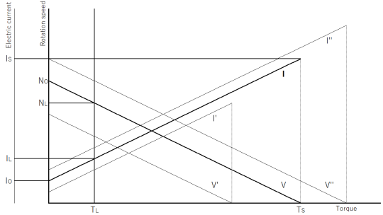
Relationship Between T-N Characteristics and Supply Voltage
The T-N characteristic (torque characteristics) graph, which represents motor performance, varies significantly depending on the supply voltage. When the supply voltage is changed, the entire T-N curve shifts parallel, and under identical conditions, the no-load speed and starting torque are generally proportional to the voltage.
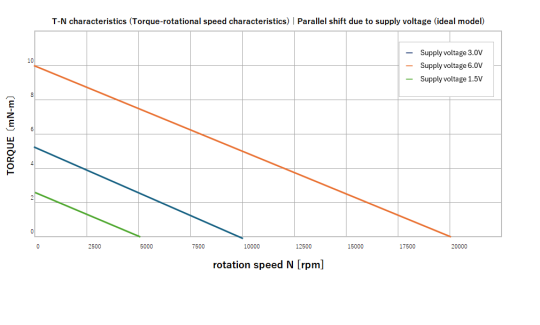
For example, under near-no-load conditions, applying 6.0 V to a motor rated at 3.0 V causes the no-load speed and starting torque to increase, theoretically, in proportion to the voltage: the no-load speed increases from 10,000 rpm to approximately 20,000 rpm, and the starting torque increases from 5.0 mN·m to approximately 10.0 mN·m.However, in practice, due to the characteristics of the magnetic circuit and the effects of heat generation, the values may not double exactly.
| Supply voltage (theoretical reference value) | No-load speed | starting torque |
| 3.0 V (rated) | 10,000 rpm | 5.0 mN·m |
| 6.0V | 20,000 rpm | 10.0 mN·m |
| 1.5V | 5,000 rpm | 2.5 mN·m |
By utilizing these characteristics, the average applied voltage (duty cycle) can be adjusted via PWM control to continuously vary the motor speed.
In product design, it is necessary to clarify the voltage range that meets the required torque and speed, and to design the power supply circuit。
Rated Voltage and Operating Voltage Range
The rated voltage is the voltage value used as the standard for evaluating the motor’s performance. The operating voltage range is set according to the product and manufacturer specifications (datasheet) and designed with power supply fluctuations in mind.
High voltages exceeding the operating voltage range can cause overheating and reduce the lifespan, while low voltages will prevent the motor from achieving the required torque and speed.
| Voltage Conditions (Reference Values) | Impact on the Motor |
| Exceeding Rated Voltage (Over +10%) | Overheating, accelerated brush wear, reduced lifespan |
| Within rated voltage range (±10%) | Normal operation, lifespan ensured |
| Below rated voltage (less than -10%) | Insufficient torque, reduced speed, decreased performance |
When performing motor selection, it is necessary to consider power supply voltage fluctuations in the actual operating environment.
In battery-powered devices, motor performance degrades over time due to voltage drop.
To ensure stable operation, motor selection is important, ensuring that the motor can maintain the required performance even after a voltage drop
Challenges in Low-Voltage Operation
In battery-powered devices, motor performance degrades over time due to a drop in battery voltage. To ensure stable operation, motor selection must include a motor capable of starting even at low voltages, and circuit design must account for voltage drops.
[Major Challenges in Low-Voltage Operation]
- Malfunction due to insufficient starting voltage
- Failure to drive the load due to reduced torque
- Malfunction of control circuits or activation of protection circuits
- Reduced accuracy of battery level indication
To address these challenges, motor selection is effective. In particular, for applications requiring reliable operation, such as security equipment and medical equipment, motors with a low minimum operating voltage are essential.
In the following section, we will explain Takiron CI’s Coreless motors, which can start up from as low as 1.0V.
Takiron CI’s Coreless Motors Capable of Operation at Low Voltages
Takiron CI’s Coreless motors can start operating at a minimum voltage of 1.0V, contributing to energy savings and a long service life in battery-powered devices.
Contents of this section
- Low-Voltage Start-Up Characteristics of Coreless Motors
- Benefits of energy-saving and high efficiency design
- Application-Specific Case Studies and Product Selection
Thanks to its coreless design, which eliminates the need for an iron core, this motor delivers virtually zero cogging torque and smooth rotation, while also achieving high efficiency despite its compact size.
In applications where battery lifespan determines product value—such as medical equipment, security equipment, and hobby products—this motor enables stable operation in low-voltage ranges, which was difficult to achieve with conventional motors.
Low-Voltage Start-Up Characteristics of Coreless Motors
The coreless structure, which does not use an iron core, eliminates cogging torque and iron loss during startup, allowing operation to begin at a minimum voltage of 1.0 V.
This characteristic allows operation to continue even when the battery level is low, reducing the frequency of battery replacement.
| Item | Our Company’s Conventional Product | Takiron CI 4mm-diameter Coreless motors |
| Minimum startup voltage | 2.0V~3.0V | 1.0V |
| Cogging at startup | Present | Virtually zero |
| Operation at low voltage | Unstable | Stable |
For example, in battery-powered electronic locks, conventional motors may become unstable as battery voltage drops. In contrast, Takiron CI’s Coreless motors include models capable of starting at 1.0 V, contributing to stable operation even in the low-voltage range.
This characteristic is particularly important for applications that require reliable operation, such as security equipment and medical equipment.
The low-voltage starting performance enabled by the coreless structure directly contributes to improved product reliability.
Benefits of Energy-Saving and High-Efficiency Design
The combination of low-voltage operation and high efficiency enables a significant reduction in electric current consumption.
Since battery-powered medical equipment and security equipment require long periods of continuous operation, this power-saving feature directly improves product reliability.
[Main Benefits of Power-Saving Design]
- Extended lifespan (reduced replacement frequency)
- Compact and lightweight products due to a smaller power supply
- Reduced heat generation (simplified thermal design)
- Increased continuous operating time
Takiron CI’s coreless motors eliminate iron loss associated with iron cores, allowing for reduced electric current consumption while maintaining equivalent output.
For example, in portable medical equipment, this extends the operating time per charge, leading to improved patient convenience. In hobby products, even small batteries can provide sufficient operating time, making it possible to achieve both product miniaturization and improved performance.
Application-Specific Case Studies and Product Selection
Takiron CI has a proven track record of adoption in applications that rely on battery power, such as electronic locks, portable medical equipment, and hobby products.
We offer customization tailored to specific applications and maintain a flexible production system capable of handling everything from small batches to mass production, allowing us to assist you from the development stage.
| Application Fields | Required Characteristics |
| security equipment | Low-voltage startup, long service life |
| medical equipment | High precision, low power consumption |
| optical equipment | Low vibration, high responsiveness |
| Hobby products | Compact, high torque |
When developing products, it is necessary to clearly define the required torque, rotational speed, and voltage range in order to perform optimal motor selection.
At Takiron CI, we listen to your product requirements and propose the optimal motor from our extensive lineup.
We provide comprehensive support, from supplying samples during the prototyping stage to quality control during mass production, making us a trusted development partner.
Summary

A proper understanding of the relationship between motors and voltage is the foundation for proper motor selection in product development.
By grasping the interrelationships between voltage, speed, torque, and electric current, and understanding the meaning of T-N characteristics and rated voltage, you will be able to determine the motor specifications that meet your requirements.
In battery-powered devices in particular, starting performance at low voltages and power consumption determine the product’s operating time; therefore, Takiron CI’s Coreless motors, which can operate from as low as 1.0 V, are a strong choice.
Take advantage of the low-voltage starting characteristics and high efficiency provided by the coreless structure to extend the lifespan of the battery and improve product reliability.
Product Information & Inquiries
For more details on C.I. Takiron’s micro motor products, please visit the website below.
- Product Site: https://cik-ele.com/en/
- Coreless Motors: https://cik-ele.com/en/products/list/coreless_motor/
- Brushless Motors: https://cik-ele.com/en/products/list/brushless_motor/
- Geared Motors: https://cik-ele.com/en/products/list/gearhead/
- Encoders: https://cik-ele.com/en/products/list/encoder/
If you are having trouble selecting a small motor for your product development, please feel free to contact us via the inquiry form. Our technical staff will discuss your application and requirements with you and propose the optimal solution.
- Inquiries: https://cik-ele.com/en/contact/
The basic formulas for DC motors used in this article are based on the following academic and technical literature:
- Voltage equation: “V = Eb+ IaRa“
National Institute of Technology, “D.C. Motor” https://nit-edu.org/wp-content/uploads/2021/09/ch-29-Dc-motor.pdf
- Torque equation: “T = Kt× I”
MIT OpenCourseWare, “Magnetic Electro-Mechanical Machines”