


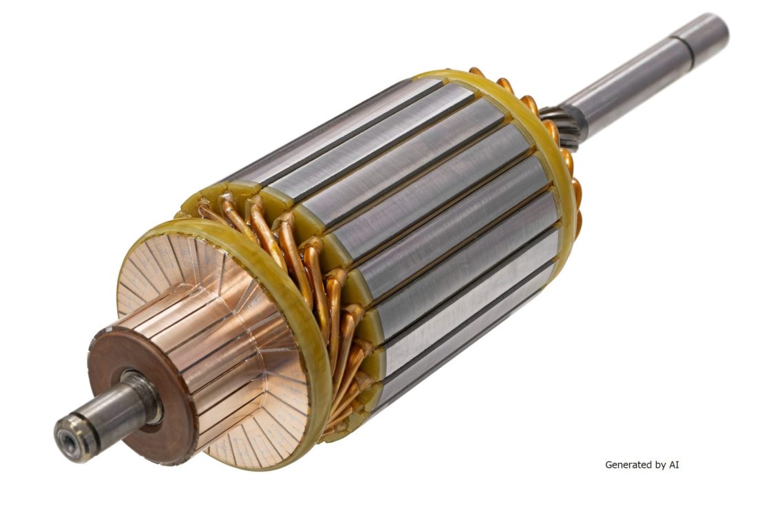
When installing a motor into equipment, an inappropriate shaft mounting method can result in torque transmission loss due to slippage and abnormal vibration. In the worst-case scenario, there is a risk of accidents caused by parts falling off or equipment damage. In medical equipment and industrial precision equipment, even the slightest mounting defect can affect product performance and safety; therefore, it is essential to select the correct mounting method based on the shaft shape.
Three main types of motor shafts are used: D-cut shafts, round shafts, and keyway shafts. Each differs in the fastening methods that can be applied, the torque they can transmit, and the difficulty of machining. This article explains the characteristics of each shaft shape and typical fastening methods (such as screw fastening, clamp fastening, key fastening, and pin fastening) from a technical perspective, and presents selection criteria based on specific applications.
| Supervised by: C.I. TAKIRON Corporation Electronic Devices Sales Group This article has been supervised based on the advanced technical expertise and insights we have cultivated since our founding in 1919 as a leading company in plastic processing. Our department continuously analyzes market trends and the latest technologies in ultra-compact, high-precision micro motors, focusing on providing high-value-added information to designers and developers. As a team of experts with in-depth knowledge of product characteristics, we support our customers’ problem-solving and technological innovation by delivering accurate and practical content. |
Differences in Mounting Methods by Motor Shaft Shape
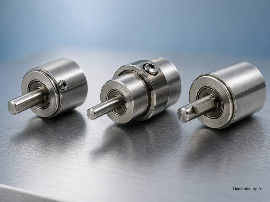
The fastening methods for motor shafts vary depending on the shaft shape. Here, we explain the structure and fastening methods for the three representative shaft shapes.
Contents of This Section
- Structure and Mounting Methods for D-Cut Shafts
- Structure and Mounting Methods for Round Shafts
- Structure and Mounting Methods for Keyway Shafts
Understanding the characteristics of each shaft shape will enable you to select the appropriate mounting method based on design conditions and loads.
Structure and Mounting Methods for D-Cut Shafts
A D-cut shaft has a flat surface (D-cut face) machined into a portion of the shaft, and fastening is performed using this flat surface. Since there is no standardized specification for D-cut dimensions and they often depend on the manufacturer’s specifications, it is necessary to verify the machined shape of the shaft on a case-by-case basis. There are also double D-cut shafts with D-cuts on both sides of the shaft.
The main fastening methods applicable to D-cut shafts are as follows.
| Fastening Method | Features |
| Screw Fastening | The most common method, in which the flat section is secured with a set screw (grip screw) |
| Clamp fastening | A method in which the shaft is clamped between machined parts and secured with screws, enabling a strong, secure fastening |
| Face Pressure Fastening | A method in which the shaft is clamped and tightened. Round shafts provide higher clamping force than D-cut shafts; verification is necessary as D-cut shafts may exhibit play |
| Pin fastening | A method in which a hole is drilled into the shaft and a pin is press-fitted; care must be taken to avoid reducing the shaft’s strength |
C.I. Takiron Corporation’s geared motors are available with D-cut shafts and can be used in combination with the fastening methods described above.
Structure and Mounting Methods for Round Shafts
Since round shafts have a continuous circular outer circumference, their clamping characteristics vary depending on the clamping method selected. Common clamping methods include surface pressure clamping, screw clamping, and pin clamping. In particular, surface pressure clamping—such as with clamps—allows the entire circumference of the shaft to be uniformly restrained, enabling stable torque transmission under appropriate clamping conditions.
Structure and Fastening Methods of Keyway Shafts
Keyway shafts are shaft configurations that ensure high torque transmission capacity through the use of keys. They are used in applications where high torque is generated on the output shaft. This design involves fitting a key (a protruding metal component) into a groove on the shaft and the rotating component, enabling reliable torque transmission.
Key dimensions are standardized under JIS specifications; once the shaft diameter is determined, the key dimensions are also determined. However, machining the keyway on the rotating component requires specialized machine tools such as those listed below.
| Equipment Name | Features |
| Broaching Machine | Suitable for mass production of internal keyways. Requires specialized machinery and specialized cutting tools |
| Slotter | Capable of machining internal keyways. Machining speed is slower than that of a broaching machine |
| Wire EDM Machine | Capable of handling complex shapes. Machining takes a long time and is costly |
Since machining options are limited, it is necessary to confirm machinability during the design phase. Keyway shafts are suitable for applications requiring high torque transmission, such as industrial equipment and pump drives.
*This refers to general-purpose motors, not Micromotors.
Types of Fasteners for Connecting Motor Shafts to Components
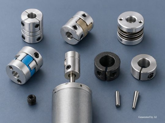
When connecting a motor shaft to a driven component, the choice of fastener can improve ease of assembly and disassembly and help compensate for alignment errors. This section explains typical fasteners and their optimal combinations with shaft geometries.
Contents of This Section
- Types of Couplings and Selection Criteria
- Features and Applications of Keyless Bushings
- Optimal Combinations of Shaft Shapes and Fastening Components
The selection of fasteners depends not only on the shape of the motor shaft but also on the transmitted torque and maintenance frequency.
Types of Couplings and Selection Criteria
A coupling is a mechanical component that connects the drive shaft (such as a motor shaft) to the driven shaft to transmit power. It is used when extending a motor shaft or when machining the motor shaft directly is undesirable. Products are available that support various fastening methods, such as screw fastening, face-pressure fastening, and key fastening.
The following are the main types of couplings.
| Type | Features |
| Rigid Type | No flexural deflection and high torsional rigidity. Requires high-precision shaft alignment |
| Oldham Type | Tolerates eccentricity and angular misalignment, and is easy to assemble. Specifications must be verified for high-speed rotation applications |
| Disc Type | This design minimizes backlash and is capable of high-speed rotation. Simple construction makes installation and removal easy |
| Jaw-type | The elastic element absorbs shock and vibration. High versatility |
When selecting a model, choose the type that best suits your design conditions based on the allowable torque, misalignment tolerance, and rotational speed. For medical equipment and industrial equipment, it is also efficient to consider the ease of motor replacement during maintenance. C.I. Takiron Corporation’s Micromotors are available with D-cut or round shafts and can be connected to various types of couplings.
Features and Applications of Keyless Bushings
A keyless bushing is a component that directly secures a shaft to a rotating element (boss), such as a gear or pulley. It utilizes the “wedge principle” created by its tapered shape and features a structure that transmits torque through surface pressure. When the bolt is tightened, the tapered surface generates high frictional force between the shaft and the boss, enabling a secure fastening even without keyways.
Keyless bushings offer the following advantages.
[Main Advantages of Keyless Bushings]
- Reduced stress concentration on the shaft and boss due to the elimination of keyway machining
- Easy installation and removal by simply retightening the bolt
- High torque transmission capacity ensured by friction generated across the entire contact surface
These fasteners are used in applications requiring frequent installation and removal, such as industrial pumps and conveyors.
Optimal Combination of Shaft Shape and Fasteners
By appropriately matching the shaft shape with the fastener, you can achieve the optimal fastening method for your specific application. The following summarizes the recommended fasteners and fastening methods for each shaft shape.
| Shaft Shape | Recommended Fasteners and Methods | Suitable Applications |
| D-Cut Shaft | Couplings secured by screws or clamps | Easy to connect to standard compact motors and perform component selection |
| Keyway shaft | Couplings with key fastening | High-load applications where high torque is generated on the output shaft |
Additionally, for high-load applications, the combination of a keyway shaft and a key-type coupling is suitable. We recommend selecting a combination that matches the application conditions and verifying performance during the prototyping stage.
*This refers to general motors and does not apply to our company’s Micromotors.
Practical Considerations for Motor Shaft Mounting Methods
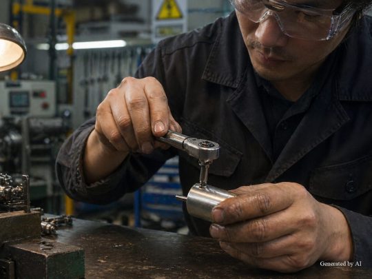
Each method of securing a motor shaft has its own practical considerations. Understanding the characteristics of each fastening method and taking appropriate measures during the design phase helps prevent problems after assembly.
Topics Covered in This Section
- Mechanisms Behind Screw Loosening and Countermeasures
- Machining Difficulty and Cost Issues Associated with Key Fastening
- Risks of Strength Reduction and Scope of Application for Pin Fastening
Please identify the weaknesses and countermeasures for each fastening method and select the fastening method that best suits your application conditions.
Mechanisms of Loosening in Screw Fastenings and Countermeasures
Screw fastening (set screws) is a simple method, but there is a risk of loosening. Because set screws have low clamping force, they are suitable for low-load applications, but careful consideration is required for high-load applications.
One of the main causes of screw loosening is a decrease in friction between the seating surface and the component. Loosening patterns can be classified into two types: cases where the nut loosens without rotating (initial loosening, sinking, vibration, temperature differences) and cases where the nut rotates backward and loosens.
One method to prevent loosening is to periodically retighten the set screw to restore the axial force. Additionally, using spring washers or toothed washers, tightening with double nuts, and applying threadlocker to the screw thread are also effective measures.Since set screws lack a seating surface, the washers typically used with standard bolts and nuts cannot be applied. To prevent set screws from loosening, apply a thread-locking adhesive (threadlocker) to the threaded portion. In the case of D-cut shafts, the design presses the flat surface against the screw, making them less prone to loosening than round shafts; however, for applications subject to high loads, consider switching to clamp fastening or surface pressure fastening.
Machining Difficulty and Cost Issues with Keyed Fasteners
Key fastening is a method that ensures high torque transmission capacity, but machining keyways requires specialized equipment. In particular, machining keyways on rotating components is limited by the availability of compatible equipment, which can make it difficult for individuals or small-scale factories to implement.
The equipment required for keyway machining and its characteristics are as follows.
| Equipment Name | Features |
| Broaching Machine | Suitable for mass production of internal keyways. High equipment acquisition cost |
| Slotter | Capable of machining internal keyways. Machining speed is slower than that of a broaching machine |
| Wire EDM Machine | Capable of handling complex shapes. Machining takes a long time and is costly |
Generally, machining costs and assembly labor tend to increase. It is necessary to confirm the feasibility of keyway machining during the design phase and to understand the capabilities of the machining facility in advance. For high-load applications where reliable torque transmission is required, it is appropriate to use key fasteners even if this entails higher costs.
Risks of Reduced Strength and Scope of Application for Pin Fastening
Pin fastening involves drilling a hole in the shaft and press-fitting a pin into it. It is important to note that the strength of the shaft at the drilled location decreases, leading to stress concentration. If machining accuracy is poor, the pin cannot be properly press-fitted, and the fastening itself will fail.
Careful consideration is required if sufficient strength calculations and machining accuracy cannot be ensured. However, for DIY projects where a more secure fastening than set screws is desired, using knock pins (such as parallel pins or tapered pins) is another option. This is a viable choice for DIY robots and prototypes.
Furthermore, since C.I. Takiron Corporation’s coreless motors lack an iron core, they are inherently free from cogging (rotational irregularities) and exhibit low vibration during operation. By considering vibration characteristics during the motor selection phase, it is possible to design a system that reduces the load on the fastening points
Summary
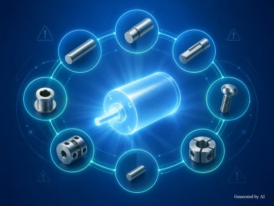
The mounting method for the motor shaft and the gearhead’s output shaft must be selected appropriately based on the shaft shape (D-cut shaft, round shaft, keyway shaft) and application conditions. The D-cut shaft is a shape commonly used in compact gearboxes ( ) and is typically combined with screw fastening or clamping. Round shafts allow for full-circumferential contact, making them well-suited for ensuring high torque transmission capacity when combined with surface-pressure fastening methods such as clamping.Keyway shafts can ensure high torque transmission capacity and are suitable for high-torque applications.
While screw fastening is simple, there is a risk of loosening; key fastening, while robust, is limited by the availability of machining equipment in practical applications. Utilizing fastening components such as couplings and keyless bushings can further improve installability and maintainability.
Please understand the characteristics of each shaft shape, as well as the advantages and considerations of each fastening method, and consider the optimal combination from the design stage.
Product Information & Inquiries
For more details on C.I. Takiron’s micro motor products, please visit the website below.
- Product Site: https://cik-ele.com/en/
- Coreless Motors: https://cik-ele.com/en/products/list/coreless_motor/
- Brushless Motors: https://cik-ele.com/en/products/list/brushless_motor/
- Geared Motors: https://cik-ele.com/en/products/list/gearhead/
- Encoders: https://cik-ele.com/en/products/list/encoder/
If you are having trouble selecting a small motor for your product development, please feel free to contact us via the inquiry form. Our technical staff will discuss your application and requirements with you and propose the optimal solution.
- Inquiries: https://cik-ele.com/en/contact/