Electrical circuit diagram symbols (referred to as “electrical diagram symbols” in JIS) are standards and rules that represent components used in electrical circuits—such as power supplies, resistors, capacitors, transistors, and motors—using standardized graphical representations. In Japan, these are defined as JIS C 0617 under the Japanese Industrial Standards and are harmonized (MOD) with the international standard IEC 60617.
In product development and maintenance, designers and manufacturing personnel use circuit diagram symbols as a common language to ensure accurate communication of information. In the design of control circuits for Micromotors, a precise understanding of electrical circuit diagram symbols is crucial because it directly impacts design quality.
This article provides an easy-to-understand explanation of electrical circuit symbols, covering everything from the basics to the different types and practical application tips.
| Supervised by: C.I. TAKIRON Corporation Electronic Devices Sales Group This article has been supervised based on the advanced technical expertise and insights we have cultivated since our founding in 1919 as a leading company in plastic processing. Our department continuously analyzes market trends and the latest technologies in ultra-compact, high-precision micro motors, focusing on providing high-value-added information to designers and developers. As a team of experts with in-depth knowledge of product characteristics, we support our customers’ problem-solving and technological innovation by delivering accurate and practical content. |
目次:
What Are Electrical Circuit Symbols?

This section explains the basic definitions of electrical circuit symbols, the background of their standardization, and the benefits of using them.
Contents of This Section
- Definition of Electrical Circuit Diagram Symbols
- Standardization According to JIS Standards
- Benefits of Using Electrical Circuit Diagram Symbols
Electrical circuit diagram symbols serve as one of the foundations for accurate information exchange among designers, and their uniform use based on JIS standards is required.
Definition of Electrical Circuit Diagram Symbols
Electrical circuit diagram symbols are standardized graphical representations of components and devices that make up electrical circuits, such as power sources, switches, resistors, and motors. The JIS C 0617 series of standards defines a circuit diagram as “a line drawing illustrating the circuits of systems, sub- systems, equipment, and components, showing the interconnections of multiple symbols to represent their functions.”
In product design and maintenance settings, these symbols enable engineers both in Japan and abroad to accurately interpret design drawings and are widely used as a common language.
Standardization under JIS Standards
In Japan, JIS C 0617 was established in 1997, advancing the standardization of electrical circuit symbols in accordance with the international standard IEC 60617. The previous standard, JIS C 0301, was abolished in 1999, and the industry transitioned to the new JIS standard.
After being revised in 2011, JIS C 0617 underwent “confirmation” procedures in 2015 and 2020—which involved no substantive changes—and was revised again in December 2024 for the first time in approximately 14 years. Creating drawings that comply with the new JIS standard facilitates smoother technical collaboration with overseas manufacturers.
| Topics | Old JIS | New JIS |
| Standard Number | JIS C 0301 | JIS C 0617 |
| Corresponding International Standards | IEC 117 | IEC 60617 |
| Year of Revocation/Adoption | Withdrawn in 1999 | Enacted in 1997 (Revised in 2024) |
Unification with the new JIS standards ensures compatibility between domestic and international technical documents.
Benefits of Using Electrical Circuit Symbols
Using electrical circuit diagram symbols allows for a visual understanding of complex circuit configurations, helping to prevent design and wiring errors. The JIS C 0617 series consists of 13 parts and is characterized by its systematic organization of a wide range of symbols, covering everything from passive components to semiconductors and the generation and conversion of electrical energy.
Since this enables the transmission of technical information across language barriers, it facilitates smooth communication even in international projects. Correct use of standardized symbols improves the readability of drawings and enhances the efficiency of design reviews and maintenance work.
Types of Electrical Circuit Diagram Symbols
Electrical circuit diagrams feature a wide variety of symbols corresponding to the functions and applications of components.
Topics Covered in This Section
- Power Source Symbols and Power Supply Symbols
- Switch Symbols and Control Symbols
- Types of Motor Symbols
Accurately understanding the meaning of each symbol will improve your ability to read circuit diagrams and enhance the precision of your designs in practical applications.
Power Source Symbols and Power Supply Symbols
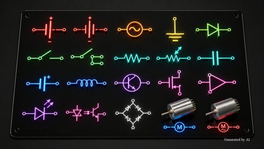
For DC power supplies (batteries), power symbols consist of two parallel lines of different lengths. AC power sources are represented by a sine wave symbol.
| Types of Power Sources | Characteristics of Symbols |
| DC power supply (Battery) | Represented by parallel lines, with the longer line indicating positive and the shorter line indicating negative |
| AC Power Source | Represented by a sine wave inside a circle |
Since DC power supply symbols are frequently used in Micromotor drive circuits, it is essential to have a thorough understanding of them, including the rules for indicating polarity.
Switch Symbols and Control Symbols
Switch symbols are selected based on the contact configuration. Single-pole single-throw (SPST) is the most basic switch symbol and is used to control the ON/OFF state of a single circuit. Double-pole double-throw (DPDT) is used in situations where two circuits need to be switched simultaneously.
The JIS C 0617 standard specifies “make contacts” (commonly referred to as “a” contacts) and “break contacts” (commonly referred to as “b” contacts) as graphical symbols for contacts; these contact symbols are combined to form motor control control circuits and other systems.
Types of Motor Symbols
The basic form of a motor symbol is the general symbol for rotating machinery, represented by the letter “M” placed within a circular frame. To distinguish between different types of electric motors, qualifying symbols such as “DC” or “AC,” as specified in JIS C 0617-2, are added.
[Classification of Major Motor Symbols]
- DC motors: The letter “M” inside a circle, with a DC qualifying symbol appended
- AC motors: The letter “M” inside a circle with the AC qualifying symbol appended
Tips for Mastering Electrical Circuit Symbols

Here are some specific tips for using electrical circuit symbols effectively in practical applications.
Contents Covered in This Section
- Use symbols compliant with JIS standards
- Utilize drafting software and templates
- Applying Them in Motor Control Control Circuits
Selecting symbols accurately in accordance with standards and utilizing design support tools will improve drafting efficiency.
Using Symbols Compliant with JIS Standards
When creating circuit diagrams, it is standard practice to use the new JIS symbols compliant with JIS C 0617. Although symbols from the old JIS standard (JIS C 0301) were discontinued in 1999, they are still occasionally used in certain industries and in older equipment drawings.
Drawings that mix old and new symbols can mislead readers and potentially lead to design errors. Standardizing on the new JIS symbols ensures consistency with the international standard IEC 60617, making it easier to exchange technical documents with overseas partners.
It is effective to formalize the transition to the new JIS symbols as an internal design rule and incorporate this as a checkpoint during drawing reviews.
Utilize CAD Software and Templates
Utilizing electrical CAD software and templates can improve drafting efficiency while maintaining symbol consistency. The following is a list of representative software programs and their JIS compliance status.
| Software Name | Features |
| AutoCAD Electrical | Comes standard with a symbol library compliant with JIS standards |
| ACAD-DENKI | Japanese-made electrical control design CAD featuring electrical symbols compliant with JIS C 0617 and JSIA 118 |
| BJ-Electrical | An electrical CAD application that runs on BricsCAD or AutoCAD |
Using the symbol library included with CAD software helps prevent errors caused by manually drawing symbols. Additionally, Newcom distributes JIS C 0617-compliant electrical symbols in DXF format free of charge, allowing them to be used with CAD software that supports this format.
By preparing templates for each project, you can maintain consistent drawing quality even when multiple designers are involved.
Used in Motor Control Control Circuits
When designing drive circuits for Micromotors, circuit diagrams that accurately combine power supply symbols, motor symbols, and control circuit symbols are required. For example, in a DC motor forward/reverse circuit, it is common to combine motor symbols with relay contact symbols and switch symbols to represent the control of the rotation direction.
By correctly distinguishing between motor symbols and switching device symbols as specified in JIS C 0617, the design intent is clearly communicated to third parties. Even when using Coreless motors or Brushless motors, creating drawings based on standardized circuit diagram symbols helps streamline design verification and maintenance work. For technical questions regarding product selection, please contact us via the C.I. Takiron Corporation inquiry form.
Summary

Electrical circuit symbols are internationally standardized graphical symbols used to visually represent electrical circuits. Using symbols compliant with JIS C 0617 allows you to simultaneously improve design accuracy and facilitate technical communication.
By accurately understanding the meanings of various symbols—such as power supply, switch, and motor symbols—and utilizing CAD software and templates, you can improve your practical circuit diagram drafting skills.
In the design of Micromotor drive circuits as well, the correct use of standardized circuit diagram symbols leads to improved design quality and maintenance efficiency.
Product Information & Inquiries
For more details on C.I. Takiron’s micro motor products, please visit the website below.
- Product Site: https://cik-ele.com/en/
- Coreless Motors: https://cik-ele.com/en/products/list/coreless_motor/
- Brushless Motors: https://cik-ele.com/en/products/list/brushless_motor/
- Geared Motors: https://cik-ele.com/en/products/list/gearhead/
- Encoders: https://cik-ele.com/en/products/list/encoder/
If you are having trouble selecting a small motor for your product development, please feel free to contact us via the inquiry form. Our technical staff will discuss your application and requirements with you and propose the optimal solution.
- Inquiries: https://cik-ele.com/en/contact/