

The ability to accurately measure and control a motor’s rotational speed is critical, as it directly impacts equipment performance and stable operation (required specifications).
“I want to know the formula for calculating rotational speed.”
“I want to understand how voltage and torque affect rotational speed”
“I want to explore methods for achieving precise speed control”
To address these technical challenges, this article provides a technically grounded explanation—ranging from the basic calculation formula for DC motor rotational speed to the factors affecting rotational speed, how to interpret T-N characteristics (torque characteristics) and how to use PWM control and feedback control for practical speed control. We provide information that will be useful to engineers in fields where reducing speed fluctuations and maintaining stable speed are critical, such as medical equipment and optical equipment.
| Supervised by: C.I. TAKIRON Corporation Electronic Devices Sales Group This article has been supervised based on the advanced technical expertise and insights we have cultivated since our founding in 1919 as a leading company in plastic processing. Our department continuously analyzes market trends and the latest technologies in ultra-compact, high-precision micro motors, focusing on providing high-value-added information to designers and developers. As a team of experts with in-depth knowledge of product characteristics, we support our customers’ problem-solving and technological innovation by delivering accurate and practical content. |
目次:
How to Calculate the Rotational Speed of a DC Motor
The rotational speed of a DC motor is calculated using a formula derived from its equivalent circuit. By understanding the basic formula—which utilizes the applied voltage, armature electric current, and motor-specific constants—you can predict the rotational speed under various operating conditions.
Topics Covered in This Section
- How to Calculate Rotational Speed from the Equivalent Circuit
- How to Determine Rotational Speed from the T-N Characteristic
- The Difference Between Rotational Speed and RPM
Below, we will explain the process step by step, from deriving the calculation formula to reading the T-N characteristic curve, and clarifying the terminology.
Calculating Rotational Speed from the Equivalent Circuit
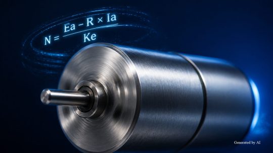
The rotational speed of a DC motor can be derived from the voltage equation of its equivalent circuit. In the equivalent circuit of a Brushed DC motor connected to a power source, the following relationship holds between the supply voltage Ea [V], the armature resistance R [Ω], the armature electric current Ia [A], and the motor’s back EMF Ec [V].
| Symbols | Symbol | Unit |
| Ea | Supply voltage | V |
| R | Armature resistance | Ω |
| Ia | 電 Armature electric current | A |
| Ec | Counter-EMF (= Ke × N) | V |
| Ke | Generation constant (back-EMF constant) | V/rpm |
| N | Rotational Speed | rpm |
The voltage equation for the equivalent circuit is expressed as “Ea = Ia × R + Ec.” Since the counter-EMF Ec is proportional to the rotational speed N, giving “Ec = Ke × N,” rearranging for N yields the following equation:
N = (Ea − R × Ia) / Ke
From this equation, we can see that the higher the applied voltage Ea, the higher the rotational speed N; conversely, as the armature electric current Ia increases, the voltage drop due to armature resistance (R × Ia) becomes larger, causing the rotational speed to decrease. Note that when expressed in SI units (Ke: V/(rad/s), Kt: N·m/A), the counter-EMF constant Ke and the torque constant Kt are physically equivalent.
This property stems from the fact that a motor is a device that converts electrical energy into mechanical energy and vice versa. Similarly, for Coreless motors, the relationship Ke = Kt holds when expressed in SI units, and the same equation can be applied to calculate rotational speed.
Reading Rotational Speed from the T-N Curve
The T-N characteristic (torque-speed characteristic) is a performance graph showing the relationship between the load torque and rotational speed of DC motors. Torque T [mNm] is plotted on the horizontal axis and rotational speed N [rpm] on the vertical axis; the relationship between the two is treated as a straight line sloping downward to the right.
Combining the rotational speed equation “N = (Ea − R × Ia) / Ke,” derived from the equivalent circuit described above, with the torque equation “T = Kt × Ia” (where Kt is the torque constant [mNm/A]), yields the following equation for the T-N characteristic:
N = Ea / Ke − (R / (Kt × Ke)) × T
As this equation shows, the T-N characteristic is treated as a downward-sloping straight line as a typical approximation. The rotational speed when the load torque is zero is defined as the no-load speed (N0), and the characteristic is such that the rotational speed decreases as the load torque increases. The torque at the point where the rotational speed becomes zero is called the stall torque (T0); if the load exceeds this value, the motor cannot maintain rotation and will stop.
[How to Read T-N Characteristics]
- No-load speed (N0): Rotational speed under no-load conditions (generally close to the maximum)
- Stall torque ( Ts ): The torque at the point where rotational speed reaches zero (stopped)
- Operating Point : The intersection point where the rotational speed corresponds to the actual load torque
The T-N characteristic is a fundamental piece of performance information listed in motor specifications and catalogs. Please use it to predict the rotational speed under operating conditions in advance and to perform motor selection.
Understanding the Difference Between Rotational Speed and Rotation Count
Rotational speed and revolutions per minute (RPM) are terms used interchangeably in motor specifications and catalogs. JIS B 6010 defines revolutions per minute as “the number of revolutions per unit time,” which refers to the same physical quantity as rotational speed. It is expressed in units of rpm (revolutions per minute) or min⁻¹, indicating the number of revolutions per minute.
Motor manufacturers’ specifications and catalogs often use the terms “rotational speed” and “revolutions per minute” interchangeably. For example, a technical explanation from one manufacturer defines “rotational speed” as “the number of times the motor shaft rotates per minute,” using the units r/min or rpm.
Regardless of the terminology used, as long as the unit is rpm or min⁻¹, it refers to the same physical quantity; therefore, checking the units when comparing specifications from multiple manufacturers will help avoid confusion.
Factors Affecting the Rotational Speed of DC Motors
The rotational speed of a DC motor fluctuates during operation due to various factors. As indicated by the formula “N = (Ea − R × Ia) / Ke,” the applied voltage, armature electric current (which varies depending on the load torque), and motor constants all affect the rotational speed.
Topics Covered in This Section
- The Effect of Voltage Changes on Rotational Speed
- Variations in Rotational Speed Due to Load Torque
- The Inverse Relationship Between Speed and Torque
A proper understanding of these factors will enable you to identify the causes of speed deviations from expectations during actual operation and apply this knowledge to perform appropriate motor selection and set optimal drive conditions.
The Effect of Voltage Changes on Rotational Speed
In DC motors, increasing the applied voltage raises the rotational speed. According to the calculation formula “N = (Ea − R × Ia) / Ke,” when the supply voltage Ea increases, the armature electric current Ia rises immediately after the voltage is raised, causing the motor to accelerate ( ). As the motor accelerates, the counter-EMF rises, causing the armature electric current to decrease until a new equilibrium state is reached; this mechanism ultimately results in an increase in rotational speed.
In terms of the T-N characteristic, increasing the supply voltage causes the entire graph to shift parallel upward, resulting in an increase in both no-load speed and holding torque. Conversely, lowering the voltage shifts the graph downward, causing both speed and torque to decrease. This parallel shift is a major advantage of DC motors, as it allows the entire T-N curve to be adjusted by varying the voltage.
However, applying a voltage exceeding the rated voltage can cause heat generation in the motor and degradation of its insulation, leading to a shorter lifespan. Be sure to check the motor’s rated specifications when setting drive conditions.
Variation in Rotational Speed Due to Load Torque
As load torque increases, the rotational speed of a DC motor decreases. To output torque commensurate with the load, the motor must increase the armature electric current Ia, which results in a larger voltage drop (R × Ia) due to armature resistance. Consequently, the counter-EMF Ec decreases, causing the rotational speed to drop.
The changes in rotational speed and armature electric current for each load condition are summarized below.
| Load Condition | Armature Electric Current | Rotational Speed |
| No Load | Minimum | Maximum (no-load rotational speed) |
| Rated load | Rated Value | Rated Speed |
| Overload | Excessive | Significant drop (may cause stoppage) |
As a typical approximation, we can see that rotational speed decreases as load torque increases.
In reality, even under no-load conditions, factors such as motor friction prevent the load from being completely zero, so the electric current does not drop to zero even at maximum speed. Under overload conditions, the motor may stop (lock up), leading to burnout due to overheating of the windings. Perform motor selection using a rated torque suitable for the application and also consider measures for overload protection.
Inverse Relationship Between Rotational Speed and Torque
In DC motors, rotational speed and torque have a trade-off (negative correlation) relationship: as one increases, the other decreases. At high rotational speeds, the output torque decreases, while at low rotational speeds, the motor generates high torque.
The mechanical output P [W] of a motor can be calculated as the product of rotational speed and torque; the formula using angular velocity ω [rad/s] is as follows:
P = T × ω [ = T × (2πN / 60) ]
For a given output, reducing the rotational speed increases torque, while increasing the rotational speed decreases torque. For example, with a motor rated at 0.5 W, halving the angular velocity theoretically doubles the output torque. By utilizing this characteristic and using a gearhead to reduce the motor’s high rotational speed, it is possible to achieve low-speed, high torque output characteristics without changing the motor control settings.
Depending on the application, either high speed and low torque or low speed and high torque may be required. If the balance between rotational speed and torque does not meet the application’s requirements, adopting Geared motors—which incorporate a gearhead—is also a viable option.
Methods for Controlling Motor Rotational Speed
There are both electrical and mechanical methods for controlling the rotational speed of a DC motor. The optimal motor control method must be selected based on the precision, response speed, cost, and installation space required by the application.
Topics Covered in This Section
- How to Adjust Voltage Using PWM Control
- How to Stabilize Speed Using Feedback Control
- How to Adjust Rotational Speed Using a Gearhead
Below, we explain the three methods widely used for DC motor speed control, along with their principles and characteristics.
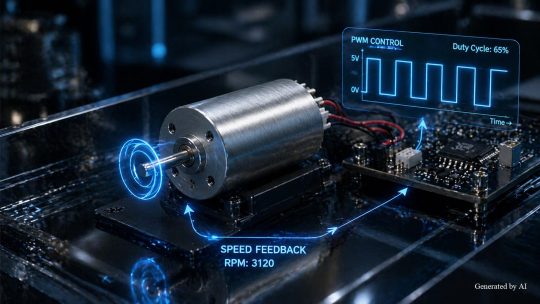
Adjusting Voltage Using PWM Control
PWM (Pulse Width Modulation) control is a method that rapidly switches the voltage on and off, varying the proportion of on-time (duty cycle) to adjust the average voltage (equivalent applied voltage) to the motor. If the switching frequency is sufficiently high, the motor’s inductance component smoothes out the electric current, resulting in stable rotation at an average voltage corresponding to the duty cycle.
The relationship between the duty cycle and rotational speed is summarized below.
| Duty Cycle | Average Voltage (for a 12V supply voltage)) | Effect on Rotational Speed (Depends on conditions) |
| 25% | Approx. 3 V | Decrease |
| 50% | Approx. 6 V | Around the midpoint |
| 75% | Approx. 9 V | Upward direction |
| 100% | 12V | Maximum direction |
Since PWM control adjusts voltage by switching the power device on and off, it offers lower power loss and higher efficiency compared to the resistive voltage drop method. PWM is commonly used to drive both Brushed DC Motors and Brushless DC Motors and, depending on the design requirements, can be implemented with a relatively simple configuration.
Stabilizing Speed with Feedback Control
Feedback control is a method that detects the actual rotational speed using sensors such as encoders or tachogenerators and automatically adjusts the drive voltage based on the deviation from the target speed. With PWM control alone (open-loop control), the rotational speed fluctuates when the load changes; however, by combining it with feedback control, speed fluctuations can be minimized even when the load varies, allowing the motor to track the target speed.
The basic configuration of feedback control is
“Setting the Target Speed”
→ “Calculating the deviation in the controller”
→ “Adjust the voltage to the motor via the drive circuit”
→ “Detect actual speed with a sensor”
→ “Feedback to the controller”
This is the control loop. There are many examples of implementing PID control (proportional, integral, and derivative) using a microcontroller, and the combination of these three elements allows for adjusting speed tracking performance and disturbance suppression.
[The Three Elements of PID Control]
- P (Proportional) Control: Correction proportional to the magnitude of the error
- I (Integral) Control: Correction to eliminate accumulated deviation
- D (Derivative) Control: Correction proportional to the rate of change of the error
In applications requiring high speed stability, such as medical equipment and optical equipment, motor characteristics with low cogging, as well as the encoders’ resolution and detection accuracy, affect the performance of speed feedback.
Converting Rotational Speed with a Gearhead
A gearhead (reduction gear) is a device that converts the high rotational speed of a motor into low speed and high torque through gear meshing. By taking into account the reduction ratio, transmission efficiency, and load conditions, the rotational speed and torque can be adjusted to the target range without significantly altering the electrical control.
For example, when a gearhead with a reduction ratio of 100:1 is combined with a motor, if the motor’s rotational speed is 10,000 rpm, the output shaft’s rotational speed becomes 100 rpm, and the torque theoretically increases 100-fold (in practice, losses occur depending on the gear’s transmission efficiency).
100:1 = 10,000 rpm : 100 rpm
When used in conjunction with electrical PWM control or feedback control, a wider range of speeds and torques can be achieved.
s, which integrate the gearhead and motor into a single unit, are known as Geared motors. At C.I. Takiron Corporation, we handle Geared motors in addition to Coreless motors and Brushless motors. We have established a system to propose the optimal configuration for your application, ranging from motor selection to Geared motors.
Summary
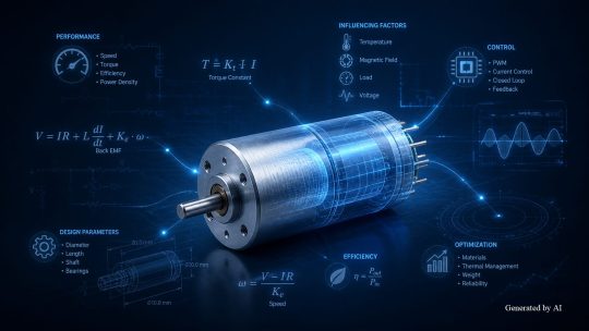
The rotational speed of a DC motor is calculated using the equivalent circuit equation “N = (Ea − R × Ia)/Ke” and varies depending on the applied voltage, armature resistance, back-EMF constant, and the armature electric current, which changes in response to the load torque. In the T-N characteristic curve, changes in voltage cause the graph to shift approximately in parallel, illustrating a correlation where the rotational speed decreases as the load torque increases.
There are several methods for controlling rotational speed, including voltage adjustment via PWM control, speed stabilization via feedback control, and mechanical speed reduction using a gearhead; the appropriate method is selected based on the required precision and cost. In the development of precision equipment, motor selection plays a critical role in achieving the required performance, as it involves selecting a motor with smooth rotational characteristics and low cogging, as well as excellent responsiveness.
Product Information & Inquiries
For more details on C.I. Takiron’s micro motor products, please visit the website below.
- Product Site: https://cik-ele.com/en/
- Coreless Motors: https://cik-ele.com/en/products/list/coreless_motor/
- Brushless Motors: https://cik-ele.com/en/products/list/brushless_motor/
- Geared Motors: https://cik-ele.com/en/products/list/gearhead/
- Encoders: https://cik-ele.com/en/products/list/encoder/
If you are having trouble selecting a small motor for your product development, please feel free to contact us via the inquiry form. Our technical staff will discuss your application and requirements with you and propose the optimal solution.
- Inquiries: https://cik-ele.com/en/contact/