


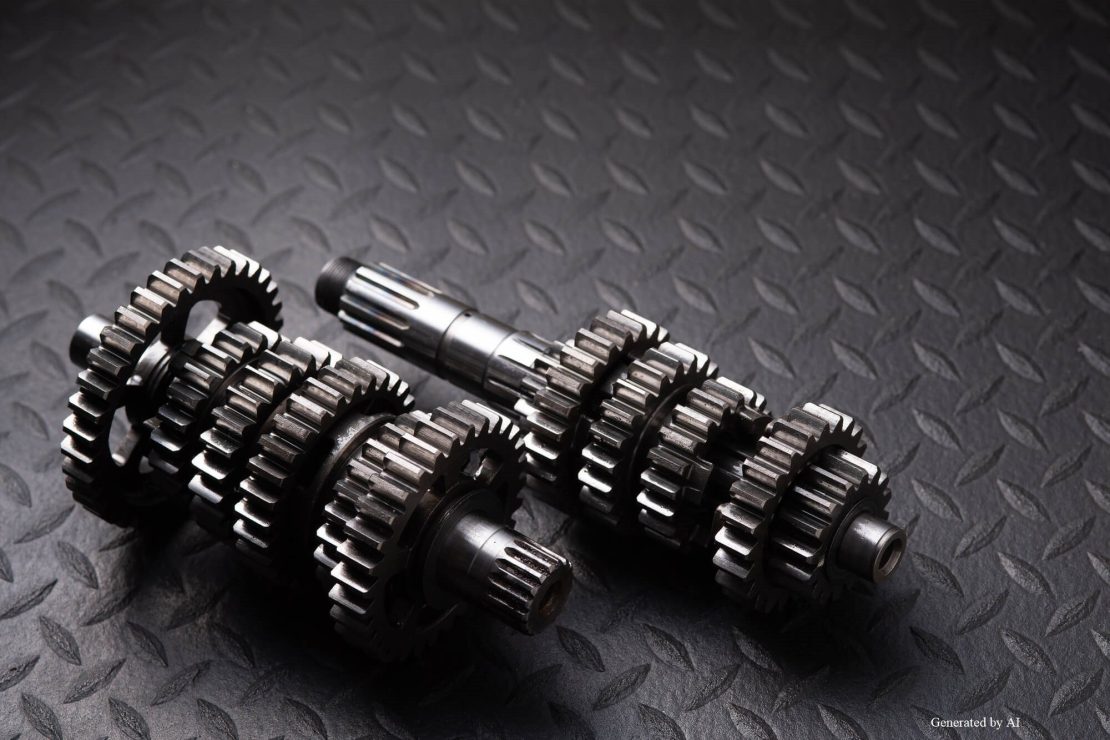
In the design of products powered by motors—such as industrial equipment, medical equipment, and optical equipment—the “gear reducer” is a critical component that determines performance. It is incorporated into many devices to achieve high torque output and precise positioning control that cannot be obtained from a motor alone.
However, many design engineers likely have questions such as “What exactly is a gear reducer?”, “Which type should I choose?”, and “What are the optimal specifications for my product?” Selecting the wrong gear reducer can lead to risks such as operational failures due to insufficient torque, design changes caused by oversized units, and even a shortened lifespan for the product.
In this article, we will explain the practical knowledge needed during the specification review stage, covering everything from the basic mechanisms of gearheads to the characteristics of different types, actual applications, and key selection criteria. *
*We do not sell gearheads (gear reducers) as standalone units. We develop and sell Geared motors, which combine a gearhead with a motor.
| Supervised by: C.I. TAKIRON Corporation Electronic Devices Sales Group This article has been supervised based on the advanced technical expertise and insights we have cultivated since our founding in 1919 as a leading company in plastic processing. Our department continuously analyzes market trends and the latest technologies in ultra-compact, high-precision micro motors, focusing on providing high-value-added information to designers and developers. As a team of experts with in-depth knowledge of product characteristics, we support our customers’ problem-solving and technological innovation by delivering accurate and practical content. |
What Is a Gear Reducer? Basic Principles and Necessity
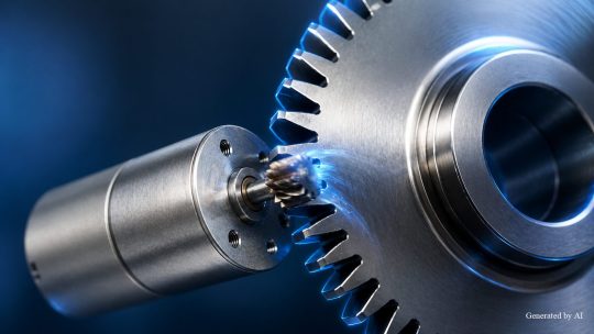
A gear reducer is a device that uses mechanisms such as gears to reduce the rotational speed of a motor and increase torque (rotational force). Since rotational speed and torque are inversely proportional, reducing the speed allows for the generation of greater force.
Contents of this section
- Basic Structure and Operating Principles of Reducers
- The Relationship Between Reduction Ratio and Torque
- Limitations of a Motor Alone and the Need for a Gear Reducer
This principle is the same as that of a bicycle’s gear system: a heavy gear allows for faster riding but makes it difficult to climb hills, while a light gear reduces speed but enables climbing hills with greater force. Attempting to achieve high torque with a motor alone requires a larger unit, but by combining it with a reduction gear, even a small motor can provide the necessary torque, enabling smaller equipment, lower power consumption, and precise positioning control.
Basic Structure and Operating Principle of Gearboxes
The most basic structure of a reduction gear consists of two gears with different numbers of teeth. When power is transmitted from the smaller gear (input side) to the larger gear (output side), the rotational speed is reduced in proportion to the ratio of the number of teeth.
For example, if the input gear has 10 teeth and the output gear has 50 teeth, the reduction ratio is 5:1. While the rotational speed is reduced to 1/5, the torque increases approximately fivefold. This mechanical principle of gearing makes it possible to obtain a large output from a small input. By combining multiple stages of gears, even higher reduction ratios can be achieved, allowing for the design of an optimal balance between torque and rotational speed tailored to the specific application.
The Relationship Between Reduction Ratio and Torque
The reduction ratio is a numerical value representing the ratio of the output shaft’s rotational speed to that of the input shaft. The higher the reduction ratio, the slower the rotational speed and the greater the torque. However, the actual output torque obtained is the product of the reduction ratio and the transmission efficiency.
The transmission efficiency of gear reducers varies by manufacturer and specifications, but is typically around 95–98% for spur gears and 96–98% for planetary gears.Efficiency decreases as the number of reduction stages increases. For example, in a reducer with a reduction ratio of 10:1 and a transmission efficiency of 95%, if the motor torque is 0.1 Nm, the output torque is approximately 0.95 Nm (0.1 × 10 × 0.95). Selecting the appropriate reduction ratio for the application is key to maximizing the performance of the equipment.
Limitations of the Motor Alone and the Need for a Gearbox
Attempting to achieve high torque with a motor alone requires making the motor itself larger, which leads to problems such as increased weight, higher power consumption, and rising costs. Furthermore, directly controlling a high-speed motor reduces positioning accuracy and makes fine control difficult.
By incorporating a gear reducer, it is possible to achieve space-saving design and reduce costs in the equipment. Furthermore, reducing the rotational speed improves control resolution, enabling precise positioning.
Types, Features, and Applications of Gearboxes
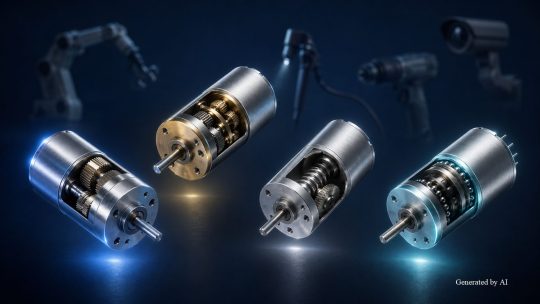
Gear reducers are classified into several types based on the type and arrangement of the gears used. Representative examples include spur gear reducers, planetary gear reducers, worm gear reducers, and cycloidal gear reducers.
Topics Covered in This Section
- Main Types of Gear Reducers, Their Features, and Applications
- Differences Between Gearheads and Geared Motors
- Main Application Fields and Specific Examples of Geared Motors (Motors Integrated with Gearboxes)
Spur gear reducers feature a simple structure, offer excellent cost performance, and are suitable for a wide range of applications.Planetary gearheads are compact and suitable for high torque transmission, making them ideal for applications with limited space. Worm gearheads offer high reduction ratios and holding torque, while helical gearheads are used in applications requiring high-precision positioning. At Takiron C , we offer Geared motors that combine spur or planetary gearheads with Coreless motors, and we have a proven track record of adoption primarily in the medical, optical, and security fields.
Main Types, Features, and Applications of Gearboxes
| Type | Features | Example Applications |
| Spur Gear Reducer (Spur Gear Type) | Simple structure, low manufacturing costs, and excellent quiet operation. High transmission efficiency (95–98%) | General-purpose industrial equipment |
| Planetary Gear Reducer (Planetary Gear Type) | Multiple gears share the load simultaneously, enabling a compact design and high torque. The input and output shafts can be coaxially arranged | medical equipment Robotics optical equipment |
| Worm gear reducer | Achieves a high reduction ratio in a single stage, features self-locking to prevent reverse rotation (some models can operate in reverse under certain conditions). | Lifting Mechanism Hoisting Machinery |
| Wave Gear Reducer | Offers ultra-high-precision positioning with virtually zero backlash, but is expensive | Industrial robot Semiconductor manufacturing equipment |
Spur gear types feature a simple structure, excellent mass-production capabilities, and high cost-performance. Planetary gear types are suitable for applications with limited space because the input and output shafts can be coaxially arranged; they are also used in the gearheads of C.I. Takiron Corporation’s Geared motors.
The Difference Between Reducers (Gearheads) and Geared Motors
A gearhead refers to a device mounted directly on the output shaft of a motor. On the other hand, “Geared motors” are products in which the gearhead and motor are integrated into a single unit. C.I. Takiron Corporation sells geared motors that combine compact size with high transmission efficiency.
Integrating the motor and reducer simplifies installation, reduces the required floor space, and streamlines wiring. Since the reduction ratio and mounting dimensions can be optimized for the motor’s characteristics, this contributes to improving the efficiency of the entire system. C.I. Takiron Corporation offers these as Geared motors (integrated motor-reducer units), which also help reduce our customers’ design workload.
Main Application Fields and Specific Examples of Geared Motors (Motors Integrated with Gearboxes)
Geared motors are used in a wide range of fields. The following are examples of their main applications.
[Main Application Fields for Geared Motors]
Industrial robot: Articulated robots, collaborative robots
Medical equipment: Endoscope camera drives, dental handpieces
Power Tools: Electric drills, impact drivers, nail guns
Optical equipment: Camera autofocus mechanisms, pan-tilt mechanisms for surveillance cameras
Security equipment: Electronic locks, automatic gates
Hobby Applications: Radio-controlled servo motors
C.I. Takiron Corporation’s geared motors can contribute to the medical and optical fields, where compact size and high precision are essential. For example, endoscopic cameras require precise positioning within the narrow confines of the body, making compact planetary gearheads with minimal backlash ideal. Additionally, in electronic locks where low power consumption and a long service life are essential, high-efficiency geared motors may prove particularly effective.
Key Considerations When Selecting a Geared Motor
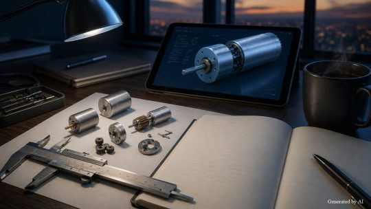
When selecting a gear reducer, it is necessary to comprehensively evaluate multiple factors, including required torque, reduction ratio, backlash, size, and operating environment.
Topics Covered in This Section
- How to Calculate Required Torque and Reduction Ratio
- The Relationship Between Backlash and Positioning Accuracy
- Selection Criteria Based on the Operating Environment
First, calculate the required torque based on the load of the driven object, and determine the motor output and reduction ratio.Next, if positioning accuracy is required, select a model with low backlash; if installation space is limited, consider a compact planetary gear type. Additionally, operating conditions such as the operating temperature range, dust and water resistance, shock resistance, and noise level are important selection criteria. At C.I. Takiron Corporation, we engage with customers from the specification planning stage to propose the optimal combination of motor and gearhead, ensuring high quality and flexible customization.
How to Calculate Required Torque and Reduction Ratio
The first step in selecting a gear reducer is calculating the torque required to drive the target object. The required torque is calculated based on factors such as the load weight, travel distance, acceleration, and coefficient of friction.
The basic calculation formula is as follows.
[Calculation of Required Torque]
Calculation of Motor Output Torque
Motor Output Torque = Motor Rated Torque × Reduction Ratio × Gearbox Efficiency
Calculation Example: Motor rated torque 0.2 Nm, reduction ratio 10:1, gear unit efficiency 95%
Motor output torque = 0.2 × 10 × 0.95 = 1.9 Nm
Determining Required Motor Torque
Required Motor Torque (Nm) = Motor Shaft Equivalent Torque (Nm) × Safety Factor
Calculation example: For a load torque of 0.5 Nm and a safety factor of 2.0
Required motor torque = 0.5 × 2.0 = 1.0 Nm
By taking the safety factor into account and selecting specifications with a margin of safety greater than the calculated value, long-term reliability can be ensured. C.I. Takiron Corporation’s Micromotors are compact yet capable of precise torque control at the mNm level, making them ideal for high-precision applications such as medical equipment and optical equipment.
The Relationship Between Backlash and Positioning Accuracy
Backlash refers to the gap (play) between gears and directly affects positioning accuracy. For medical equipment and optical equipment requiring high-precision control, low-backlash specifications are essential depending on the application.
Planetary gear systems are structurally well-suited for minimizing backlash, while helical gear systems can achieve near-zero backlash. When making an actual selection, it is necessary to balance cost and application requirements. For example, in camera autofocus mechanisms, where precise control of lens position is required, planetary gearheads with low backlash are suitable. C.I. Takiron Corporation’s products meet these requirements and are highly regarded in the medical and optical fields.
Selection Criteria Based on Operating Environment
Selection criteria vary depending on the operating environment, including operating temperature range, dust and water resistance (IP rating), shock resistance, and noise level. The main requirements for each application field are listed below.
| Application Field | Main Specifications |
| medical equipment | Low noise, sterilizable, biocompatibility |
| Tools | High impact resistance, dustproof performance |
| security equipment | Low-temperature start-up capability and long service life designed for outdoor installation |
| optical equipment | Low Vibration, High-Precision Positioning |
In medical equipment, low noise is prioritized out of consideration for patients; in power tools, impact resistance capable of withstanding on-site environments is essential; and in security equipment, cold-start capability designed for outdoor installation is critical. At C.I. Takiron Corporation, we customize Geared motors to suit our customers’ specific operating environments, offering high quality and flexible support ranging from small-lot prototyping to mass production. Please feel free to consult with us from the specification planning stage.
Summary

A gear reducer is a device that reduces the rotational speed of a motor while increasing torque, and is utilized in a wide range of fields, including industrial equipment, medical equipment, and optical equipment. It enables high torque and precise control that cannot be achieved with a motor alone, playing a crucial role in achieving both compactness and high performance in equipment.
By understanding the characteristics of each type—such as spur gear and planetary gear types—and comprehensively evaluating factors like required torque, backlash, and operating environment, it is possible to select the optimal gear reducer. At C.I. Takiron Corporation, we provide optimal solutions combining Coreless motors and gear reducers, supporting our customers’ product design from the specification planning stage.
Product Information & Inquiries
For more details on C.I. Takiron’s micro motor products, please visit the website below.
- Product Site: https://cik-ele.com/en/
- Coreless Motors: https://cik-ele.com/en/products/list/coreless_motor/
- Brushless Motors: https://cik-ele.com/en/products/list/brushless_motor/
- Geared Motors: https://cik-ele.com/en/products/list/gearhead/
- Encoders: https://cik-ele.com/en/products/list/encoder/
If you are having trouble selecting a small motor for your product development, please feel free to contact us via the inquiry form. Our technical staff will discuss your application and requirements with you and propose the optimal solution.
- Inquiries: https://cik-ele.com/en/contact/