When using inductive loads such as motors and relays, the back-EMF generated the moment the electric current is interrupted can cause serious damage to power supplies and control circuits. Appropriate countermeasures against back-EMF are essential, particularly in fields that require high reliability, such as medical equipment and industrial equipment.
By correctly understanding the principles behind back EMF and grasping its specific effects on motors and power supplies, you can incorporate effective countermeasures from the design stage.
To achieve safe and reliable product designs, let’s deepen our understanding of back EMF.
| Supervised by: C.I. TAKIRON Corporation Electronic Devices Sales Group This article has been supervised based on the advanced technical expertise and insights we have cultivated since our founding in 1919 as a leading company in plastic processing. Our department continuously analyzes market trends and the latest technologies in ultra-compact, high-precision micro motors, focusing on providing high-value-added information to designers and developers. As a team of experts with in-depth knowledge of product characteristics, we support our customers’ problem-solving and technological innovation by delivering accurate and practical content. |
目次:
Principles and Mechanisms of Back-EMF Generation
Understanding how back EMF is generated is the first step toward safe product design.
This article covers both the transient voltage spikes (induction kicks) that occur when electric current is interrupted and the rotational back electromotive force (Back EMF) that continuously occurs while the motor is rotating.
Below, we will explain these mechanisms in detail from three perspectives.
Topics Covered in This Section
- Energy Stored in Coils and the Role of the Magnetic Field
- The relationship between changes in electric current and back EMF
- Characteristics of back EMF during motor rotation
By understanding these elements, you can predict the impact of counter-electromotive force on your products and incorporate effective countermeasures from the design stage.
Energy Stored in Coils and the Role of Magnetic Fields
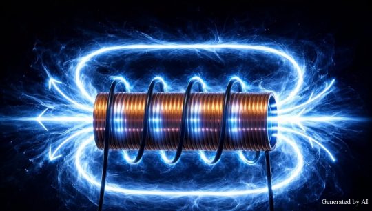
When an electric current flows through a coil, a magnetic field is generated around it, and electrical energy is stored as magnetic energy. This stored energy is rapidly released when the electric current is interrupted, generating counter-electromotive force.
Since the strength of the magnetic field is proportional to the number of coil turns and the magnitude of the electric current flowing through it, motors handling high currents store more energy, resulting in a larger counter-electromotive force.
Takiron CI’s Coreless motors, due to their structure lacking an iron core, have low winding inductance, which can help reduce the transient voltage spikes generated when the electric current is interrupted. This reduces the load on protective circuits and enables safer product designs.
Equation Relating Change in Electric Current and Back-EMF
The magnitude of the back-EMF can be expressed using a calculation formula.
Formula for back-EMF: V = -L × (dI/dt)
| Symbols | Meaning | Unit |
| V | Magnitude of counter-electromotive force | V (volt) |
| L | Coil inductance | H (henry) |
| dI/dt | Rate of change of electric current per unit time | A/s (ampere-seconds) |
From this equation, we can see that the more rapid the change in electric current and the greater the inductance, the higher the counter-electromotive force generated.
In switching operations, the electric current changes in an extremely short time—on the order of a few microseconds—so the value of dI/dt becomes very large, resulting in the generation of a high-voltage counter-electromotive force.
From this relationship, V = -L × (dI/dt), we can see that there are two approaches to suppressing the transient voltage spikes generated during electric current interruption: “reducing inductance” or “slowing the rate of electric current change.”
By adopting a motor with a low-inductance design, such as a Coreless motor, it becomes easier to reduce the transient voltage spikes generated during interruption of the electric current
Characteristics of Back-EMF During Motor Rotation
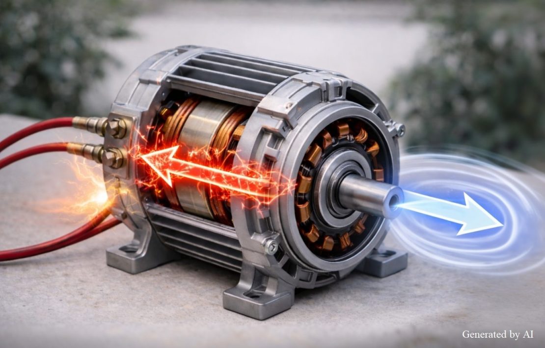
When a DC motor rotates, a “rotational back-EMF” is continuously generated in the coils.
This rotational back-EMF is a voltage induced in the coils by the motor’s rotation; it acts in the opposite direction of the applied voltage to suppress the motor electric current.
As the rotational speed increases, the rotational back-EMF increases, and because the difference from the applied voltage decreases, the electric current flowing through the motor decreases.
As a result, the rotational speed naturally stabilizes, contributing to speed control and the maintenance of stable rotation in DC motors.
Depending on the product specifications, coreless motors may have low winding inductance, which can help reduce transient voltage spikes during shutdown. However, since the actual suppression level depends on motor constants and the drive circuit (clamping method), verification is necessary during the design phase.
Reducing transient voltage spikes alleviates the load on the control circuit, enabling stable control even during high-speed start-stop operations. Particularly in applications involving frequent start-stop cycles, this characteristic directly contributes to improved product reliability.
The Impact of Back-EMF on Motors and Power Supplies
When back-EMF occurs, it can cause serious damage to the control circuit and power supply system.
Below, we explain the specific effects of back-EMF from three perspectives.
Contents of this section
- Damage to transistors and FETs
- Backflow and Voltage Surge in Power Supply Circuits
- Malfunction of control circuits and noise generation
Preventing these effects can ensure the long-term reliability of your products.
Damage to transistors and FETS
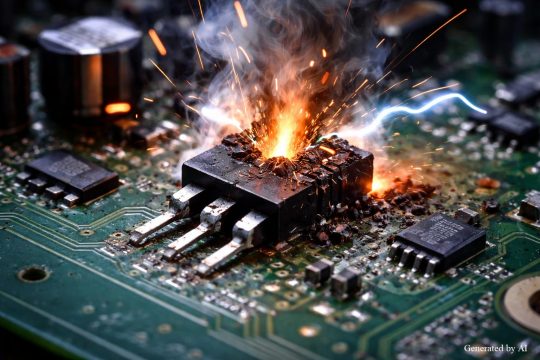
Switching devices in motor drive circuits are at risk of being destroyed by overvoltage caused by back-EMF.
If a voltage exceeding the collector-emitter breakdown voltage of a transistor or the drain-source breakdown voltage of an FET is applied, the device will instantly break down, and a large electric current may flow, potentially causing thermal destruction.
Operating the device beyond its rated voltage not only significantly shortens its lifespan but, in the worst-case scenario, may cause it to fail immediately upon first operation, potentially compromising the reliability of the entire product.
Reverse Current Flow and Voltage Rise in the Power Supply Circuit
If electric current flows back to the power supply due to back-EMF, the supply voltage may rise, causing the overvoltage protection circuit to activate. This is particularly likely to occur in bridge circuits, where reverse electric current paths are easily formed, potentially leading to a drop in power supply output or a complete system shutdown.
Measures to prevent reverse current are essential for power supply protection, but adding protection circuits increases costs and complicates the circuit design.
By adopting a motor with a low-inductance design, reverse current caused by back-EMF can be reduced, enabling a simple and highly reliable power supply design
Control Circuit Malfunctions and Noise Generation
Transient voltage spikes caused by back-EMF generate electrical noise, which adversely affects peripheral circuits.
This causes incorrect sensor readings and control microcontroller malfunctions, which reduces the reliability of the entire system.
By reducing the transient voltage spikes generated when the electric current is interrupted, Coreless motors minimize the noise source itself and minimize the impact on peripheral circuits.
Effective Countermeasures Against Back-EMF
To prevent back-EMF from affecting the circuit, it is essential to design an appropriate protection circuit.
There are several countermeasures available, such as diodes, Zener diodes, CR snubber circuits, and varistors, each with its own characteristics. Fundamental countermeasures based on the motor’s design are also effective.
Below, we explain effective countermeasures that can be applied in practical applications from three perspectives.
Contents of this section
- Protection Using a Single Diode
- Using Zener Diodes in Combination for Fast Recovery
- Utilizing CR snubber circuits and varistors
Selecting the optimal protection method based on application requirements and desired recovery time enables the creation of products with high reliability.
Protection Using a Single Diode
Connecting a diode in parallel with the coil is the most basic and widely used method.
It suppresses voltage rise by returning the electric current generated during reverse electromotive force to the power supply via the diode.
Features of Diode Protection Circuits
Features of Diode Protection Circuits
| Item | Description |
| Advantages | Simple circuit configuration, low cost, few components |
| Disadvantages | Long recovery time; not suitable for high-speed switching |
| Selection Criteria | Select a value that exceeds the supply voltage and accounts for surges and fluctuations (Guidelines available depending on application) |
| For low-voltage circuits | Can be used with a reverse breakdown voltage of approximately three times the supply voltage |
This method is widely adopted in applications requiring high reliability, such as medical equipment and industrial equipment.
It is important to select a diode with a reverse breakdown voltage that is at least equal to the supply voltage, while allowing sufficient margin to account for surges and design tolerances.
Use a Zener diode in combination to achieve fast recovery
By connecting a Zener diode in series with a standard diode, the clamping voltage can be increased, thereby shortening the recovery time. Since the reverse voltage applied to the coil increases, the electric current converges more quickly, making this suitable for applications requiring high-speed switching.
If the Zener diode voltage is selected incorrectly, not only will the switching device not be protected, but the Zener diode itself may be damaged; therefore, thorough verification is necessary.
Utilizing CR Snubber Circuits and Varistors
A CR snubber circuit, which combines a capacitor and a resistor, is a countermeasure that can also be used in AC circuits.
The capacitor absorbs sudden voltage changes, and the resistor dissipates the energy as heat, thereby suppressing transient voltage spikes caused by back-EMF.
Characteristics of CR Snubber Circuits and Varistors
| Countermeasures | Applicable Circuits | Main Features |
| CR Snubber Circuit | AC/DC Compatible | Smooths voltage changes and suppresses spikes |
| Varistor | AC/DC Compatible | Resistance drops sharply above a specific voltage to absorb overvoltage |
A varistor is a device whose resistance drops sharply above a certain voltage, effectively absorbing overvoltage.
In industrial equipment and security equipment, combining multiple protective components creates a system that offers higher protection.
Although CR snubber circuits increase the number of components and thus make the circuit more complex, they offer high noise suppression and minimize the impact on surrounding circuits.
Since varistors have a fast response speed and react instantly to sudden overvoltages, they are also effective for countering external noise such as lightning surges.
Summary
Back-EMF is a phenomenon that occurs when the electric current flowing through a coil changes; when a motor stops, it can result in a transient voltage spike that significantly exceeds the applied voltage (the value varies depending on L, the switching speed, and the clamping circuit).
Since this can cause serious issues—such as the destruction of transistors or FETs in the control circuit, voltage rises due to reverse current flowing back to the power supply, and control circuit malfunctions—appropriate countermeasures, such as diode protection circuits, circuits using Zener diodes, or CR snubber circuits, are essential.
When selecting a protection circuit, it is important to choose the optimal method by considering the recovery time and cost appropriate for the application. Furthermore, by taking back-EMF into account from the motor selection stage, the protection circuit can be simplified, enabling a safer and more reliable product design.
Product Information & Inquiries
For more details on C.I. Takiron’s micro motor products, please visit the website below.
- Product Site: https://cik-ele.com/en/
- Coreless Motors: https://cik-ele.com/en/products/list/coreless_motor/
- Brushless Motors: https://cik-ele.com/en/products/list/brushless_motor/
- Geared Motors: https://cik-ele.com/en/products/list/gearhead/
- Encoders: https://cik-ele.com/en/products/list/encoder/
If you are having trouble selecting a small motor for your product development, please feel free to contact us via the inquiry form. Our technical staff will discuss your application and requirements with you and propose the optimal solution.
- Inquiries: https://cik-ele.com/en/contact/