


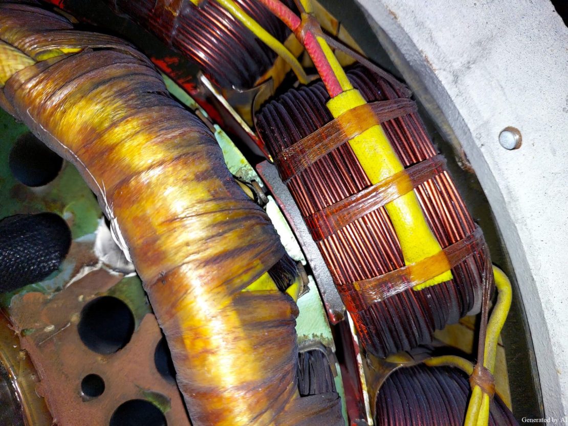
One of the most critical factors determining a motor’s performance is its “winding.” Windings consist of conductors—such as copper or aluminum wire—wound into coils. When an electric current flows through them, they generate a magnetic field. Through interaction with other magnetic fields (such as those from permanent magnets or other windings), they produce the rotational force that drives the motor, making them the heart of the motor.In motors used across a wide range of fields—from industrial motors to medical equipment, optical equipment, and security equipment—the materials, types, winding methods, and design of the windings directly impact performance, efficiency, durability, and reliability.
This article systematically explains the knowledge that B2B engineers need to know, ranging from the basic principles of motor operation to material types, manufacturing methods, selection criteria by application, resistance measurement and management, and design optimization points. For engineers involved in motor design and product development, understanding winding technology is crucial for optimal motor selection and performance maximization.
| Supervised by: C.I. TAKIRON Corporation Electronic Devices Sales Group This article has been supervised based on the advanced technical expertise and insights we have cultivated since our founding in 1919 as a leading company in plastic processing. Our department continuously analyzes market trends and the latest technologies in ultra-compact, high-precision micro motors, focusing on providing high-value-added information to designers and developers. As a team of experts with in-depth knowledge of product characteristics, we support our customers’ problem-solving and technological innovation by delivering accurate and practical content. 。 |
目次:
Basic Knowledge of Motor Winding and Types of Materials
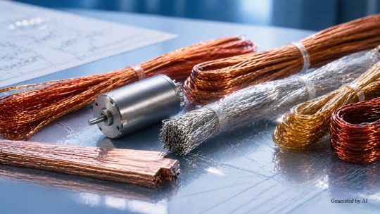
Motor windings consist of insulated wires wound into coils. When an electric current flows through them, they generate a magnetic field, and the interaction of this magnetic field produces the rotational force of the motor.
Topics Covered in This Section
- The Three Roles of Windings in Motors
- Performance Comparison of Copper and Aluminum Winding
- Types of Insulation and Selection Criteria
Winding is arranged on the stator and rotor, and the methods used vary widely depending on the type of motor. Wire materials include copper and aluminum, while insulation coatings include polyurethane, polyester, and polyester imide. The combination of these materials and insulation coatings determines the motor’s performance and reliability.
The Three Roles of Windings in Motors
Winding performs the following three critical roles in a motor.
[The Three Roles of Winding]
- Generating a magnetic field by passing electric current
- Controlling the strength and distribution of the magnetic field to determine torque and rotational speed
- Properly dissipating the heat generated (copper loss)
Since the strength of the magnetic field varies depending on the number of turns and the configuration of the windings, they are the most critical factor determining a motor’s performance. For example, increasing the number of turns strengthens the magnetic field and improves torque, but it also increases resistance. Additionally, performance characteristics can be adjusted based on the wire area product (wire diameter squared × number of turns). In medical equipment and optical equipment, the precision of this winding design directly impacts product reliability.
Performance Comparison of Copper and Aluminum Winding
The selection of winding material depends on the motor’s application and the required performance. The main characteristics of copper and aluminum windings are shown below.
| Item | Copper Winding | Aluminum Winding |
| Electrical Conductivity | High (resistivity 1.68×10⁻⁸ Ω·m) | Approx. 60% of copper |
| Specific gravity | 8.9 | 2.7 (lightweight) |
| Cost | High | Low |
| Main Applications | Compact, high-performance motors | Large and automotive motors |
Types of Insulation Coatings and Selection Criteria
The operating temperature of the environment is the most critical factor in selecting an insulation coating. The characteristics of the main insulation coatings are shown below.
| Type of Coating | Temperature Resistance | Heat Resistance Class | Main Features and Applications |
| Polyurethane (UEW) | 120℃ | Class E | Direct soldering possible; suitable for compact motors |
| Polyester (PEW) | 155℃ | Class F | Widely used in general-purpose motors |
| Polyesterimide (EIW) | 180℃ | Class H | Excellent heat resistance; used in heat-resistant general-purpose motors. |
While polyurethane wire can be soldered directly and is suitable for compact motors, it is not suitable for high-temperature environments. Polyester wire is widely used in general-purpose motors and offers well-balanced characteristics. Polyester-imide wire has excellent heat resistance and delivers stable performance even during prolonged continuous operation. Selecting the appropriate insulation coating for the specific application is a critical factor that determines the motor’s reliability and lifespan.
Motor Winding Manufacturing Methods and Application-Specific Selection
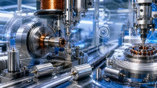
Motor windings involve various winding methods and manufacturing processes, and selection requires an understanding of their respective characteristics.
Topics Covered in This Section
- Comparison of Characteristics: Distributed Winding, Concentrated Winding, and Coreless Winding
- Proper Use of Spindle, Flyer, and Nozzle Winding Methods
- Requirements for Windings Used in Medical Device Applications, Optical Equipment, and Security Equipment
Below, we provide an easy-to-understand explanation of various winding methods, such as distributed and concentrated winding, as well as manufacturing methods like the spindle method and flyer method.
Comparison of Characteristics Between Distributed Winding, Concentrated Winding, and Coreless Winding
Motor performance characteristics vary significantly depending on the winding method. The characteristics of the three main methods are shown below.
| Winding Method | Characteristics | Advantages | Main Applications |
| Distributed Winding | Winding distributed across multiple slots | Uniform magnetic field Low torque ripple Reduced vibration and noise | Large industrial motors medical equipment |
| Concentrated winding | Concentrated windings on a single tooth | High production efficiency Less copper wire used Cost reduction | Automotive Motors Compact motors |
| Core-less winding | Core-less structure | Zero cogging torque high-speed responsiveness Smooth rotation | medical equipment optical equipment Precision equipment |
In distributed winding, the windings are distributed across multiple slots (grooves in the iron core), resulting in a uniform magnetic field. This minimizes torque ripple and is effective in suppressing vibration and noise. On the other hand, in concentrated winding, the windings are concentrated on a single tooth (a protrusion on the iron core). This structure simplifies the winding process, leading to high production efficiency, and reduces costs by minimizing the amount of copper wire used.Core-less winding, which does not use a core, produces almost no cogging, enabling smooth rotation, and features a low moment of inertia and excellent high-speed responsiveness. Thanks to these characteristics, C.I. Takiron Corporation’s core-less motors are well-suited for precision applications such as medical equipment and optical equipment.
Selecting Between Spindle, Flyer, and Nozzle Winding Methods
The selection of the manufacturing method depends on the coil shape, production volume, and precision requirements.
[Main Manufacturing Methods]
- Spindle Method: Copper wire is wound around a high-speed rotating shaft
- Flyer method: A flyer (arm) rotates relative to a fixed core
- Nozzle Winding: Achieves precise winding using specialized machinery
The spindle method involves winding copper wire around a high-speed rotating shaft and is suitable for high efficiency mass production. The flyer method, in which a flyer (arm) rotates relative to a fixed core, can handle complex shapes and large-diameter coils and is primarily used for rotor windings in commutator motors.
Additionally, nozzle winding, which uses specialized machinery to perform precise winding, is a leading choice for medical equipment and optical equipment that requires high precision. The varnish treatment applied after winding not only prevents deformation caused by vibration and heat but also serves to improve mechanical strength and insulation performance.
Winding Requirements for Medical Device Applications, Optical Equipment, and Security Equipment
Understanding the winding requirements for each application enables motor selection. The requirements for major fields are listed below.
| Field | Required Performance | Technical Requirements | C.I. Takiron Corporation’s Solutions |
| medical equipment | High-precision control | cogging-free Low vibration, low noise, and long service life | Smooth rotation achieved with Coreless motors |
| optical equipment | High-speed AF Image stabilization | High-speed responsiveness (in milliseconds) Positioning accuracy (micrometer order) | Precise control with high-response Coreless motors |
| security equipment | Battery-powered long service life | Low-voltage operation (1.0 V to 3.0 V) Energy-saving | Models available that operate at a minimum of 1.0V |
Medical equipment requires smooth rotation with virtually no cogging torque, high-precision speed control, low vibration and low noise, and a long service life.Optical equipment requires high-speed responsiveness and positioning accuracy for camera autofocus and lens drive. For security equipment, low-voltage operation (1.0V–3.0V) and long service life (reducing battery replacement frequency) are critical. C.I. Takiron Corporation’s Micromotors include models that operate at a minimum of 1.0V, providing optimal solutions tailored to the demands of each field.
Motor Winding Resistance Measurement and Design Optimization
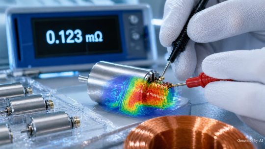
The resistance value of motor windings is the most important indicator for evaluating motor performance and quality.
Topics covered in this section
- Formulas for calculating winding resistance and measurement methods
- Resistance changes due to temperature rise and thermal design
- Optimization of winding design and customization for specific applications
Winding resistance is determined by the length, wire diameter, and electrical resistivity of the material, and directly affects the motor’s electric current, torque, heat generation, and efficiency. During the manufacturing process, continuity tests and resistance measurements are performed, and tolerance limits are set according to product specifications, standards, and manufacturer criteria. As a guideline, some cases manage resistance values within approximately ±10%.Additionally, since the resistance of copper wire increases by approximately 4% for every 10°C rise in temperature , appropriate cooling design is essential. The design process comprehensively optimizes winding materials, number of turns, wire diameter, winding method, insulation coating, and thermal management according to the specific application.
Formula for Calculating Winding Resistance and Measurement Methods
Accurate understanding and measurement of winding resistance are essential for motor quality control. Winding resistance R is calculated using the following formula.
[Formula for Winding Resistance]
R = ρ × L / A
ρ: Electrical resistivity of the material (Ωm)
L: Length of the conductor (m)
A: Cross-sectional area of the wire (m²)
Increasing the number of turns increases the winding length L, raising the resistance, while increasing the wire diameter increases the cross-sectional area A, lowering the resistance. For example, when comparing copper wires with diameters of 0.1 mm and 0.2 mm with the same number of turns, the resistance of the latter—which has four times the cross-sectional area—is calculated to decrease to approximately one-fourth that of the former.
After the winding is complete, the resistance is measured using a digital multimeter or milliohmmeter to verify that it matches the design value. Additionally, testing the insulation performance through a withstand voltage test is an essential step in quality assurance. At C.I. Takiron Corporation, we ensure high reliability under strict quality control.
Resistance Changes Due to Temperature Rise and Thermal Design
Temperature rise during motor operation significantly affects performance and lifespan. Copper wire has a temperature coefficient of 0.004/°C, meaning that a 10°C increase in temperature causes the resistance to rise by approximately 4%.
| Temperature (°C) | Temperature (°C) | Impact on Efficiency |
| 25°C (Reference) | 100% | Standard |
| 50℃ | Approx. 110% | Copper loss (I²R) increases by approximately 10% |
| 75℃ | Approx. 120% | Copper loss (I²R) increases by approx. 20% |
| 100℃ | Approx. 130% | Copper loss (I²R) increases by approximately 30% |
Since the rate of efficiency loss varies depending on the ratio of copper loss to total loss, the table above should be treated as a guideline for the increase in copper loss. During motor operation, copper loss occurs due to the current flowing through the windings, leading to heat generation; as the temperature rises, the resistance increases, and efficiency decreases.
In high-temperature environments or under high-load operation, it is essential to select insulation coatings with excellent heat resistance, such as polyester imide wire, and to incorporate cooling designs such as heat sinks or fan cooling. Additionally, varnish treatment is used to secure the windings and prevent deformation caused by thermal expansion*. Since a 10°C drop in temperature approximately doubles the lifespan, proper thermal design directly contributes to achieving a long service life for the motor.
*We offer products that utilize a bonding method for this purpose.
Optimization of Winding Design and Customization by Application
Optimizing winding designs for specific applications maximizes motor performance. The following outlines design guidelines for major applications.
| Application | Winding Method | Wire Gauge Trends | Typical Number of Turns | Design Objective |
| high torque (industrial tools) | Brushed DC (stacked or wave-wound) and concentrated-wound brushless DC are the mainstream | Select thicker wire based on the allowable electric current | Increase the number of turns to raise Kt (torque constant) | Maximizing magnetic flux density while balancing copper losses and heat generation |
| High-speed rotation (Precision equipment)) | Many concentrated windings | Select fine wire or parallel winding to suppress the skin effect | Aim to reduce the number of turns to lower Ke (back-EMF constant) | Reduction of electrical time constant |
| High-precision control (Medical/Optical) | Core-less winding | Selected with consideration for the mechanical strength of the coil | Flexible design due to low inductance | Elimination of cogging torque and smooth rotation |
For high torque applications such as industrial tools, magnetic flux density is increased by using thicker wire gauges and higher turn counts. Conversely, for high-speed rotation applications such as precision instruments, designs that minimize the number of turns to reduce back EMF are common.In medical and optical equipment, cogging-free coreless windings are prioritized to achieve high-precision control. At C.I. Takiron Corporation, we listen carefully to the specific requirements of each application and provide comprehensive support from small-lot prototyping to mass production. Our technical staff works directly with you to propose the optimal solution for your challenges.
Summary
 モータ巻
モータ巻
Motor windings are the core component that generates torque through the interaction of magnetic fields created by electric current.Copper or aluminum wire is used as the material, and heat resistance varies depending on the type of insulation coating. There are various options for winding methods and manufacturing processes, and appropriate selection based on the application is essential. Key requirements differ by field—such as high-precision control and cogging-free operation for medical equipment, and high-speed responsiveness for optical equipment. Management of winding resistance and thermal design also significantly impact performance and reliability.
At C.I. Takiron Corporation, we provide high-precision Micromotors utilizing coreless winding technology, backed by rigorous quality control and customization to meet specific requirements.
Product Information & Inquiries
For more details on C.I. Takiron’s micro motor products, please visit the website below.
- Product Site: https://cik-ele.com/en/
- Coreless Motors: https://cik-ele.com/en/products/list/coreless_motor/
- Brushless Motors: https://cik-ele.com/en/products/list/brushless_motor/
- Geared Motors: https://cik-ele.com/en/products/list/gearhead/
- Encoders: https://cik-ele.com/en/products/list/encoder/
If you are having trouble selecting a small motor for your product development, please feel free to contact us via the inquiry form. Our technical staff will discuss your application and requirements with you and propose the optimal solution.
- Inquiries: https://cik-ele.com/en/contact/