

When performing motor selection, calculating torque is an essential step. Torque is a physical quantity that represents the magnitude of the force required to rotate an object around an axis. It is closely related to a motor’s output and rotational speed, and an incorrect calculation may prevent the equipment from operating properly. Conversely, selecting a motor with excessive specifications can lead to increased costs and space constraints, so caution is required.
This article explains the basic definition of torque and the proper use of units, as well as how to apply the calculation formula “T = 9550 × P/N,” which uses output and rotational speed.We have compiled practical information ranging from the concepts of load torque and safety factors to consider when performing motor selection, to the mechanism by which Geared motors increase torque. We also cover the use of the mN·m (millinewton-meter) unit commonly used for compact motors, making this content useful for those considering the selection of Micromotors.
| Supervised by: C.I. TAKIRON Corporation Electronic Devices Sales Group This article has been supervised based on the advanced technical expertise and insights we have cultivated since our founding in 1919 as a leading company in plastic processing. Our department continuously analyzes market trends and the latest technologies in ultra-compact, high-precision micro motors, focusing on providing high-value-added information to designers and developers. As a team of experts with in-depth knowledge of product characteristics, we support our customers’ problem-solving and technological innovation by delivering accurate and practical content. |
目次:
Basics and Units to Understand Before Calculating Torque
To perform torque calculations accurately, you must first understand the basic definitions and units.
Topics Covered in This Section
- The basics of torque, calculated as the product of force and distance
- Distinguishing between the units N·m and mN·m
- The inverse relationship between torque and rotational speed
Before proceeding to the calculations for motor selection, let’s review the fundamentals step by step.
Basics of torque calculated as the product of force and distance
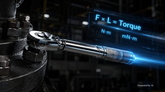
Torque is calculated as the product of “force (F) × distance from the rotation axis (L).” For example, when tightening a bolt with a wrench, the farther you grip the handle from the rotation center, the less force is required to rotate it.
Based on the same principle as a lever, the rotational force increases as the distance between the point of application of the force and the rotational axis increases. Motors with higher torque values are better suited for moving heavy objects or rotating against strong loads. When evaluating motor performance, understanding torque as the product of the force applied to the rotational axis and the distance over which it acts will make it easier to grasp the calculation formulas described later.
Distinguishing Between the Units N·m and mN·M
The international standard unit of torque is N·m (newton-meter). Torque is defined as 1 N·m when a force of 1 N (newton) is applied to a point 1 m away from the rotational axis. On the other hand, in the field of compact motors, mN·m (millinewton-meter), which is one-thousandth of N·m, is commonly used. The relationships between the main units are as follows.
| Unit | Description |
| N·m (Newton-meter) | SI base unit. The rotational force when a force of 1 N is applied to a point 1 m from the axis of rotation |
| mN·m (millinewton-meter) | One-thousandth of a N·m. Commonly used in specifications for compact motors |
| kgf·m (kilogram-force-meter) | Obsolete unit. Conversion to the current SI unit is required N·m = kgf·m × 9.80665 |
If you misread the order of magnitude between N·m and mN·m when reading specifications, your calculation results may be off by three orders of magnitude. Since torque values in the mN·m range are common during motor selection, making it a habit to verify units will help prevent calculation errors.
The Inverse Relationship Between Torque and RPM
For DC motors, torque and rotational speed generally have an inverse relationship when the supply voltage is constant. This means that when the load is heavy and high torque is required, the rotational speed decreases, while a lighter load allows for higher rotational speeds.
The S-T (speed-torque) characteristics graph visually illustrates the relationship between torque and rotational speed.On the S-T characteristic graph, torque is plotted on the vertical axis and rotational speed on the horizontal axis, with a downward-sloping straight line representing the relationship between the two. During motor selection, you can use the graph to determine whether the operating point required for the equipment (the combination of torque and rotational speed) falls within the motor’s performance range. Understanding how to read the S-T characteristic allows for an objective comparison of multiple candidate motors.
Motor Torque Calculation Formula and Method
Motor torque can be calculated using a formula based on output and rotational speed.
Topics covered in this section
- Calculating torque using the basic formula
- Understanding the three types of torque: starting torque, rated torque, and maximum torque
- Considering load torque and safety factors
We will systematically explain how to use the calculation formula and the concepts of torque necessary for selection.
Calculating Torque Using the Basic Formula
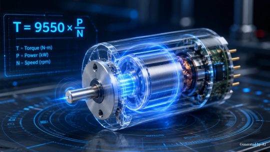
The basic formula for calculating motor torque is “T = 9550 × P / N.” T represents torque (N·m), P represents power (kW), and N represents rotational speed (rpm).The coefficient 9550 is derived by rearranging the physical relationship between power and torque: “P = T × 2πN/60 ÷ 1000.” Since 60,000 ÷ 2π ≈ 9550, torque can be calculated using just two values: power and rotational speed.
For example, for a motor with a power of 2.7 W and a speed of 17,000 rpm, T = 9550 × (2.7 ÷ 1000) ÷ 17,000 ≈ 0.0015 N·m = 1.5 mN·m.Since compact motors sometimes list output in watts (W), you must remember to convert to kilowatts (kW) when performing calculations. The result is in newton-meters (N·m), so when comparing it to motor specifications listed in millinewton-meters (mN·m), you need to multiply by 1,000. Understanding the structure of the basic formula allows you to apply it to motors with different specifications.
Understanding the Three Types of Torque: Starting Torque, Rated Torque, and Maximum Torque
There are three types of motor torque, depending on the operating phase. Starting torque is the torque generated at the moment rotation begins from a stationary state; rated torque is the upper limit that can be safely output during continuous operation; and maximum torque is the instantaneous limit that can be exerted for a short period.
| Types of Torque | Description | Main Application Scenarios |
| starting torque | Force generated when rotation begins from a stationary state | Starting with a heavy load |
| Rated Torque | The maximum value that can be safely output during continuous operation | Design standard for normal operation |
| Maximum torque | Instantaneous limit value that can be exerted for a short period | Verification of Resistance to Overload and Shock Loads |
Since the torque specifications to be verified vary depending on the product and documentation, individually check the listed items—such as starting torque, rated torque, and maximum torque—in the specification sheets and characteristic diagrams. Determining in advance which type of torque to prioritize based on the application will clarify the selection criteria.
Consider Load Torque and Safety Factor
When actually performing motor selection, it is necessary to accurately calculate the load torque required to drive the equipment. Load torque is determined not only by simple rotational resistance but also by a combination of multiple factors. The main components to consider in the calculation are as follows.
[Components of Load Torque]
- Friction torque due to friction resistance
- Moment of inertia of the rotating body
- Acceleration torque applied during acceleration
Since the approach to determining required torque and the recommended safety factor vary depending on the motor type and the manufacturer’s selection criteria, these should be verified according to the technical documentation for the specific product being used. The reason for setting a safety factor is that, in actual operating environments, an increase in load due to temperature changes and aging is anticipated. Selecting a motor whose rated torque exceeds “load torque × safety factor” ensures stable operation over the long term.
Practical Tips for Motor Selection Using Torque Calculations

To effectively apply the results of torque calculations to the practical motor selection, several practical considerations are necessary.
Topics Covered in This Section
- Reducing speed and increasing torque with Geared motors
- Comparing torque characteristics by motor type
- Paying attention to unit conversions when calculating torque for compact motors
We will outline specific points for applying calculation knowledge to practical selection tasks.
Reducing RPM and Increasing Torque with Geared Motors
Geared motors are products that integrate a motor and a gearhead. They are designed to reduce rotational speed while simultaneously increasing torque through the gears in the gearhead. The formula for calculating output torque is as follows:
Output Torque = Motor Rated Torque × Reduction Ratio × Gearbox Efficiency
The higher the reduction ratio, the lower the rotational speed, and the greater the torque. However, due to losses caused by gear transmission efficiency, the actual output torque is lower than the theoretical value. Even if a standalone motor cannot provide the required torque, motor selection for a Geared motor may allow you to meet the requirements. If torque calculations indicate that the rated torque is insufficient, using a Geared motor is an effective option.
Comparing Torque Characteristics by Motor Type
Torque characteristics vary depending on the type of motor, so it is necessary to select the type that suits the application. The torque characteristics of typical motors are as follows.
| Motor Type | Main Torque Characteristics |
| DC motors | High starting torque; torque increases in proportion to electric current |
| Brushless DC Motors | Delivers stable torque across a wide speed range and allows for easy speed control |
DC motors have the characteristic of increasing torque in proportion to electric current, making them simple to control. Brushless DC Motors have minimal mechanical contact, which reduces wear and ensures a long service life for the motors. By comparing the speed-torque characteristics of different motors and performing motor selection based on the operating conditions, you can maximize the performance of the entire system.
Be Careful with Unit Conversions When Calculating Torque for Compact Motors
For compact motors, torque values are typically in the mN·m (millinewton-meter) range; an error in converting to N·m can result in a discrepancy of three significant figures. Thoroughly verifying units from the very beginning—when reading the specifications—is an effective way to prevent motor selection errors.
Additionally, motors with a coreless structure, such as coreless motors, do not generate cogging torque (the slight rotational irregularity caused by magnetic interference between the iron core and magnets), making them suitable for precision control that leverages their smooth rotational characteristics. To perform optimal motor selection for your application and operating conditions, clearly communicate specific requirements—such as the desired torque, speed, and drive voltage—to the motor manufacturer to efficiently narrow down the list of candidates.
Summary

Motor torque is a measure of rotational force defined as “force × distance.” Using the basic formula “T = 9550 × P/N,” torque can be calculated from the output and rotational speed. When performing motor selection, it is important to understand the three types of torque—starting, rated, and maximum—and to set the safety factor in accordance with the technical data provided for the motor in question.By utilizing Geared motors, it is possible to increase torque in accordance with the reduction ratio. Since calculations for compact motors are performed in mN·m units, care must be taken with unit conversions. We hope this guide to the basics of torque calculation will help you with motor selection for your application.
Product Information & Inquiries
For more details on C.I. Takiron’s micro motor products, please visit the website below.
- Product Site: https://cik-ele.com/en/
- Coreless Motors: https://cik-ele.com/en/products/list/coreless_motor/
- Brushless Motors: https://cik-ele.com/en/products/list/brushless_motor/
- Geared Motors: https://cik-ele.com/en/products/list/gearhead/
- Encoders: https://cik-ele.com/en/products/list/encoder/
If you are having trouble selecting a small motor for your product development, please feel free to contact us via the inquiry form. Our technical staff will discuss your application and requirements with you and propose the optimal solution.
- Inquiries: https://cik-ele.com/en/contact/