


While a motor is rotating, the torque it outputs is not entirely constant. Instantaneous torque undergoes slight periodic fluctuations, manifesting as variations in rotational force. These periodic torque fluctuations are known as “torque ripple.” Significant torque ripple adversely affects equipment performance, leading to vibration, noise, reduced positioning accuracy, and degraded controllability.This is a technical challenge that cannot be ignored, particularly in fields where smooth operation and precision are directly linked to quality, such as medical equipment, optical equipment, and industrial robots. In this article, after clarifying the basic meaning of torque ripple and its difference from cogging torque, we will explain the main causes of its occurrence and methods for reducing it from the perspectives of design, control, and motor selection. This content serves as a reference for the selection and design of compact motors.
| Supervised by: C.I. TAKIRON Corporation Electronic Devices Sales Group This article has been supervised based on the advanced technical expertise and insights we have cultivated since our founding in 1919 as a leading company in plastic processing. Our department continuously analyzes market trends and the latest technologies in ultra-compact, high-precision micro motors, focusing on providing high-value-added information to designers and developers. As a team of experts with in-depth knowledge of product characteristics, we support our customers’ problem-solving and technological innovation by delivering accurate and practical content. |
目次:
What Is Torque Ripple? A Review of Basic Knowledge
Before considering countermeasures for torque ripple, it is essential to understand the phenomenon itself. By grasping the meaning of the term, distinguishing it from similar terminology, and understanding how to interpret its numerical values, you will be better prepared to understand the causes and mitigation strategies discussed later in this article. In this section, we will organize the basic knowledge of torque ripple from three perspectives to lay the groundwork for reading the rest of the article.
Contents Explained in This Section
- The Basic Meaning of Torque Ripple
- The Difference Between Torque Ripple and Cogging Torque
- Methods for Measuring and Evaluating Torque Ripple
We will examine these three perspectives in order, from the definitions of terms to evaluation metrics.
The Basic Meaning of Torque Ripple
Torque ripple refers to the amount by which the torque output by a motor fluctuates periodically rather than remaining constant while the motor is rotating. Even when the motor appears to be operating at a constant speed, the instantaneous torque is in a state of constant fluctuation depending on the rotational position and electrical conditions. When a torque sensor continuously measures the torque over one full rotation, a waveform appears that fluctuates up and down around the average value.The amplitude of this waveform represents the torque ripple; the larger the value, the less smooth the rotation. Performance issues such as vibration, noise, reduced positioning accuracy, and deteriorated controllability can often be traced back to torque ripple. This is a fundamental phenomenon that must be understood when evaluating a motor’s operational quality.
The Difference Between Torque Ripple and Cogging Torque
The difference between torque ripple and cogging torque lies in the conditions under which they occur. Cogging torque is a torque fluctuation that occurs even in permanent magnet motors when no electric current is flowing (i.e., in the de-energized state). Torque ripple refers to torque fluctuations observed while the motor is energized and running; it includes not only cogging torque but also distortions in the electric current waveform and the effects of motor control. The main differences between the two are as follows.
| Item | Cogging Torque | Torque Ripple |
| Conditions of Occurrence | Occurs even when the motor is de-energized | Occurs when powered on and driving |
| Main Causes | Structure of the iron core and magnet | Influences of electric current and control in addition to structure |
| Included range | A component of torque ripple | The total torque, including cogging torque |
Cogging torque is one component of torque ripple, and the two are in a relationship of inclusion. When evaluating torque fluctuations during operation, it is necessary to consider the total torque ripple rather than cogging torque alone. A mindset that avoids confusion and correctly distinguishes between phenomena leads to subsequent root cause analysis.
Methods for Measuring and Evaluating Torque Ripple
In the measurement and evaluation of torque ripple, it is common to express it as the percentage of the difference between the maximum and minimum torques during one revolution divided by the average torque . Expressing this as a percentage allows the degree of fluctuation to be compared using a common scale, regardless of the motor type or capacity. Direct measurement using a torque sensor is the method typically used in actual evaluations.
Furthermore, simultaneously measuring phase electric current and vibration not only reveals the magnitude of torque fluctuations but also helps identify their causes, making this a practical measurement method for understanding torque ripple. By following a procedure that measures both numerical values and waveforms, you can comprehensively understand the phenomenon and investigate its causes.
Three Main Causes of Torque Ripple

Torque ripple does not arise from a single cause but rather from a combination of multiple factors. Breaking down the mechanism of its occurrence by factor provides a useful perspective for identifying issues on-site and for considering the mitigation measures discussed later in this chapter. In this chapter, we will systematically organize the three representative factors that cause torque ripple from three perspectives: structural, electrical, and magnetic field.
Contents of This Section
- Cogging Torque is Present
- Electric current waveforms containing harmonics
- Harmonic components in the magnetic flux density
We will examine these three factors based on the premise that there is room for improvement in both design and control.
Cogging torque is present
Cogging torque is a periodic torque fluctuation that occurs even when no electric current is flowing—that is, in the de-energized state—in motors that use permanent magnets. The relative positions of the iron core’s teeth and the permanent magnets, which attract each other, change as the motor rotates, manifesting as torque pulsations. The number of cycles per revolution corresponds to the least common multiple of the number of magnetic poles and the number of slots. Cogging torque has the following characteristics.
[Characteristics of Cogging Torque]
- Occurs even when the motor is de-energized
- Interaction between stator slots and harmonics of the magnet’s induced emf
- Period determined by the least common multiple of the number of magnetic poles and the number of slots
The pulsations present when the motor is de-energized are superimposed as a component of torque ripple once the motor starts running. Since this phenomenon stems from the structure itself, it is considered the primary factor to understand when discussing torque ripple.
Electric current waveforms containing harmonics
The presence of harmonics in the electric current waveform is another factor that increases torque ripple. When driving a motor with an inverter, distortion in the electric current waveform—caused by factors such as wiring conditions—can lead to increased torque ripple. Since torque is determined by the product of electric current and magnetic flux, any deviation of the electric current waveform from an ideal sine wave causes the torque to fluctuate by the same amount.
PWM control, the basic control method for inverters, is a mechanism that generates the voltage applied to the motor by turning semiconductor switches on and off. Due to this switching operation, the electric current contains fine fluctuations with each pulse. These electric current fluctuations are converted into torque fluctuations via changes in the magnetic field, a phenomenon observed as torque ripple. This can be classified as a factor originating from the electrical input side.
*Harmonics: Components with frequencies that are integer multiples of the fundamental frequency. They cause waveform distortion.
Harmonic components in the magnetic flux density
When the magnetic flux density contains harmonic components, this leads to torque ripple as a factor on the magnetic field side. Harmonics present in the air-gap magnetic flux density cause harmonics in the armature chain magnetic flux, which ultimately manifest as torque ripple. The air gap is the slight gap between the rotor and the stator.
This phenomenon stems from the interaction between the harmonics of the permanent magnet’s induced emf and the air gap harmonics. When the magnetic field distribution deviates from an ideal sine wave, torque pulsations occur in response to rotation. Design factors such as pole arc angle, magnet shape, and magnet orientation influence the magnetic field distribution. This is the third factor on the magnetic field side, which is determined by the design around the magnets.
Three Methods for Reducing Torque Ripple

Since there are multiple causes of torque ripple, there is no single approach to reducing it. There are measures that can be taken at each stage: the design stage, the control stage, and the motor selection stage. In this chapter, we will organize the three representative methods for suppressing torque ripple in accordance with the sequence of design, control, and selection.
Contents of This Section
- Optimizing Motor Design Through Magnetic Field Analysis
- Smoothing Electric Current Waveforms Through Control
- Selecting a Coreless Motor
From upstream design to final product selection, we will examine these three methods in order.
Optimizing Motor Design with Magnetic Field Analysis
The method of optimizing motor design using electromagnetic field analysis involves an approach that minimizes the source of torque ripple from a structural perspective. The magnitude of cogging torque and harmonic components varies depending on structural elements such as the combination of the number of magnetic poles and slots, the skew of the stator and rotor, and the shape of the magnets. In design practice, it is common to use electromagnetic field simulations to numerically compare and evaluate multiple configurations.If torque waveforms for each configuration can be predicted before prototyping, it is possible to narrow down the design options to those with minimal fluctuations. Incorporating countermeasures from the early stages of design also has the advantage of reducing rework in later stages.
*Skew: A configuration in which the stator and rotor are arranged with a slight helical twist. This shifts the alignment between the magnets and slots, effectively smoothing out torque ripple.
Smoothing Electric Current Waveforms Through Control
Controlling the electric current waveform is an approach to suppressing torque fluctuations caused by the electric current during operation. Vector control is a widely adopted method. It divides the electric current flowing through the motor into d-axis and q-axis components and adjusts only the torque-generating component to bring it closer to the ideal value.If fluctuations in the electric current waveform are suppressed, fluctuations in the magnetic field will also become smoother. Additionally, reviewing the PWM carrier frequency and drive conditions is an effective measure. The advantage of the control-based approach is that adjustments can be made on the operational side without changing the design itself.
Selecting a Coreless Motor
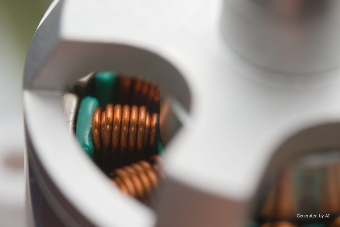
In addition to optimizing design and control, selecting a motor that matches the required characteristics also helps reduce torque ripple. A typical option is Coreless motors. Because it lacks an iron core, there is no repetitive motion caused by attraction and repulsion from magnets, resulting in virtually no cogging. The main features of Coreless motors are as follows.
[Main Features of Coreless Motors]
- Suppression of cogging due to a core-less structure
- Smooth rotational characteristics with minimal speed fluctuations
- Low vibration and noise, and high responsiveness
While motors with a core structure generate cogging torque, Coreless motors eliminate the causes of cogging at the design stage. They are a strong candidate for selection in fields such as medical equipment, optical equipment, and security equipment, where smooth rotation and quiet operation are required.
Summary
Torque ripple is a phenomenon in which the torque output by a motor fluctuates periodically during rotation. Its occurrence is caused by a combination of three factors: cogging torque, which occurs even when the motor is de-energized; harmonics contained in the electric current waveform; and harmonics contained in the magnetic flux density .To reduce torque ripple, a three-pronged approach is effective: optimizing the design through electromagnetic field analysis, adjusting the electric current waveform using vector control, and performing motor selection to ensure that the selected motor meets the required characteristics. In particular, Coreless motors, which lack an iron core, suppress cogging at the structural level, making them a strong choice for applications such as medical equipment, optical equipment, and security equipment that require quiet operation and precise control.By combining measures at each stage—design, control, and selection—torque ripple can be suppressed to levels acceptable for the specific application.
Product Information & Inquiries
For more details on C.I. Takiron’s micro motor products, please visit the website below.
- Product Site: https://cik-ele.com/en/
- Coreless Motors: https://cik-ele.com/en/products/list/coreless_motor/
- Brushless Motors: https://cik-ele.com/en/products/list/brushless_motor/
- Geared Motors: https://cik-ele.com/en/products/list/gearhead/
- Encoders: https://cik-ele.com/en/products/list/encoder/
If you are having trouble selecting a small motor for your product development, please feel free to contact us via the inquiry form. Our technical staff will discuss your application and requirements with you and propose the optimal solution.
- Inquiries: https://cik-ele.com/en/contact/