
Micromotor Product Site


Exporting to Europe, USA, and Asia.
Dealers available in North America, Europe, and Asia.
In this column, engineers from C.I. Takiron share their expertise on micro motors (coreless motors, brushless motors, and gearheads). We hope this information will assist you in selecting motors for a wide range of applications, including medical devices, industrial tools, and optical equipment.
This guide provides a detailed explanation of the technical considerations for motor selection, aimed at product development engineers and design engineers. We address common questions such as, “I don’t know which motor to choose,”and “I want to understand the difference between coreless and brushless motors.”

As medical equipment continues to become smaller and more precise, the role played by the motors that drive it is growing year by year. Compact motors are now incorporated into many devices used in medical settings—such as dental treatment units, endoscopes, electronic pipettes, and surgical assistance robots—and serve as core components that support the functionality and performance of these devices.Motors incorporated into medical equipment tend to be subject to higher performance standards than general-purpose industrial motors. To achieve the operational precision required by the equipment, it is essential to select the optimal motor for the specific application—one that offers smooth rotation, low vibration, a long service life, and a compact design. In this article, we will explain the typical applications…

Inverters are power conversion devices used across a wide range of fields, from home appliances to Industrial equipment. They are recognized as a core technology supporting both daily life and industrial operations, enabling energy saving operation of air conditioners and refrigerators, motor control in factories, and smooth acceleration and deceleration in elevators. However, there are few opportunities to systematically understand the internal structure of these devices or how they interact with motors.In this article, we will explain everything step by step—from the basic definition and mechanism of inverters to their role in motor control, real-world application examples, and key points to keep in mind during implementation. We have organized the knowledge essential for design decisions for engineers involved in motor…
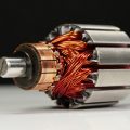
The number of poles in a motor is a basic specification indicating the number of magnetic poles formed inside the motor, and it is a parameter that influences rotational speed and torque characteristics. In the design and procurement of Micromotors, questions often arise regarding whether to choose a 2-pole or 4-pole motor, and how an increase in the number of poles affects performance.The number of poles is not a value determined in isolation; rather, the optimal solution is determined by balancing speed, torque, size, cost, and the technical requirements of each specific application. In this article, we will systematically cover the basics of motor pole count, its relationship to speed, and the approach to motor selection based on application. The…

In fields such as industrial equipment, medical equipment, and robotics, designs that balance miniaturization with the necessary torque are critical to product performance. Concerns such as “Can we increase the torque a little more while keeping the size the same?” and “We want to make the device smaller, but we’re worried about whether it can withstand the load” are recurring design challenges faced in development environments.In this article, we will provide a comprehensive explanation, covering everything from the basic mechanisms of compact high-torque Torque motors to typical methods for increasing torque, their main applications, and key points to consider during the selection process. We have also compiled frequently asked questions from the design field in a Q&A format. We hope…

The ability to accurately measure and control a motor’s rotational speed is critical, as it directly impacts equipment performance and stable operation (required specifications). “I want to know the formula for calculating rotational speed.” “I want to understand how voltage and torque affect rotational speed” “I want to explore methods for achieving precise speed control” To address these technical challenges, this article provides a technically grounded explanation—ranging from the basic calculation formula for DC motor rotational speed to the factors affecting rotational speed, how to interpret T-N characteristics (torque characteristics) and how to use PWM control and feedback control for practical speed control. We provide information that will be useful to engineers in fields where reducing speed fluctuations and maintaining…

While a motor is rotating, the torque it outputs is not entirely constant. Instantaneous torque undergoes slight periodic fluctuations, manifesting as variations in rotational force. These periodic torque fluctuations are known as “torque ripple.” Significant torque ripple adversely affects equipment performance, leading to vibration, noise, reduced positioning accuracy, and degraded controllability.This is a technical challenge that cannot be ignored, particularly in fields where smooth operation and precision are directly linked to quality, such as medical equipment, optical equipment, and industrial robots. In this article, after clarifying the basic meaning of torque ripple and its difference from cogging torque, we will explain the main causes of its occurrence and methods for reducing it from the perspectives of design, control, and motor…
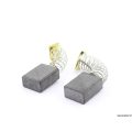
Motor carbon brushes are components that transmit electric current through sliding contact with the commutator (or slip ring); in DC motors, they work in conjunction with the commutator to maintain rotation. They are used in a wide range of equipment, from industrial motors to power tools. If carbon brushes wear out or commutation becomes unstable, it can lead to sparking or damage to the commutator, making them critical from the perspective of maintenance and downtime risks. Carbon brush materials include electrographite, natural graphite, and metal graphite, among others, and selecting the appropriate material based on the application and operating conditions is essential. Understanding how to assess lifespan and replacement timing based on brush wear, as well as how to diagnose…

Combining a motor with gears reduces rotational speed while amplifying torque, enabling output characteristics tailored to specific applications. Since motors operate at high speeds on their own, it is common practice to use a gear reduction mechanism to achieve the low-speed, high-torque output required for Industrial equipment. Failure to select an appropriate combination can lead to reduced efficiency and premature failure. The basic process involves clarifying the required torque and rotational speed during the design phase, calculating the reduction ratio, and then determining the type of gear. This article explains everything from the principle of motor operation and power transmission using gears to calculation formulas for reduction ratios and torque, the characteristics and selection criteria for different gear types, and…

Electrical circuit diagram symbols (referred to as “electrical diagram symbols” in JIS) are standards and rules that represent components used in electrical circuits—such as power supplies, resistors, capacitors, transistors, and motors—using standardized graphical representations. In Japan, these are defined as JIS C 0617 under the Japanese Industrial Standards and are harmonized (MOD) with the international standard IEC 60617. In product development and maintenance, designers and manufacturing personnel use circuit diagram symbols as a common language to ensure accurate communication of information. In the design of control circuits for Micromotors, a precise understanding of electrical circuit diagram symbols is crucial because it directly impacts design quality. This article provides an easy-to-understand explanation of electrical circuit symbols, covering everything from the basics…
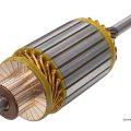
When installing a motor into equipment, an inappropriate shaft mounting method can result in torque transmission loss due to slippage and abnormal vibration. In the worst-case scenario, there is a risk of accidents caused by parts falling off or equipment damage. In medical equipment and industrial precision equipment, even the slightest mounting defect can affect product performance and safety; therefore, it is essential to select the correct mounting method based on the shaft shape. Three main types of motor shafts are used: D-cut shafts, round shafts, and keyway shafts. Each differs in the fastening methods that can be applied, the torque they can transmit, and the difficulty of machining. This article explains the characteristics of each shaft shape and typical…